*Editor's Note: This article was originally published in June 2008 and updated in October 2022.
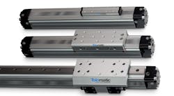
Rodless pneumatic cylinders are a great alternative to conventional rod-style air cylinders and electromechanical actuators because they both support and guide a load. This eliminates the need for other load-bearing elements and reduces costs, size, and design time. The design of rodless cylinders benefits longer stroke, space-constrained applications.
But sizing a rodless cylinder involves more than merely calculating force and stroke. The following tips can help engineers spec the best actuator for a given application.
Sizing Basics
Know the air pressure. It might seem obvious that pneumatic actuators need the proper amount of air pressure to perform up to spec, but plant air pressure isn’t always what it seems. So check the air pressure with a gauge to get an accurate reading and build in safe engineering practices.
For example, a plant may supply 100-psi (6.9 bar) air, but pressure can vary from site to site in the factory as much as 10% due to variable demand cycles. This means actual available air pressure might only be 90 psi (6.2 bar).
A 5-10% fluctuation in air pressure is quite common and can make a big difference in selecting the proper cylinder for an application. It is always best to factor in a 10% pressure loss factor from the gauge air pressure reading.
Determine working stroke and overall length. By design, a rodless actuator’s stroke lies completely within the body, giving it a smaller working footprint than conventional cylinders. But part of the actuator stroke cannot be used due to interference of internal components and the room needed to reach the end-of-stroke. This is normally referred to as the actuator’s “dead length.” Manufacturers typically indicate this dimensional information for each actuator.
To properly specify the actuator’s overall length (OAL), determine the required travel distance (working stroke), then add the given dead length at each end of the actuator. Keep in mind that auxiliary carriers and other actuator options can add to the actuator’s dead length. For example, for a cylinder with two carriers, add the total dead length, working stroke, and distance between the centers of carriers to determine the cylinder’s OAL. It is important to reference the manufacturer’s dimensional information when ordering options to see if more dead length is needed.
Right-sizing the cylinder. When it comes to cylinder sizing, bigger is not necessarily better. Too large a cylinder means excessive costs and air consumption. On the other hand, too small a cylinder may save a few dollars but will not provide the best performance or operational safety factors.
Actuators that work best are sized based on load, force, and bending-moment capacities with a safety margin factor. To properly size a cylinder, take these application parameters into consideration:
- Magnitude of load.
- Orientation of load relative to the carrier.
- Orientation of the actuator.
- Final velocity of mass and carrier.
- Working stroke length.
- Cycle rate.
Once these factors are known, determine the cylinder’s force (thrust) capacity based on available air pressure. The cylinder should perform within the specified capacity range. If the application requires performance at the maximum limit for that cylinder, consider a larger bore size or a different style cylinder with higher capabilities.
Loading Considerations
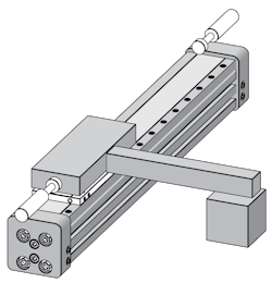
Moment loads. Often, engineers choose a cylinder based only on the force it produces. If the actuator must support an off-center load, it is important to know the bending-moment (torque) capacity of the cylinder’s bearing and load carrying system to determine if it is capable of performing consistently under the load requirements. The position and size of the load on the carrier determine the bending moments applied to the cylinder. For off-center or side loads, find the distance from the load’s center of mass to the center of the cylinder’s carrier and calculate the resulting bending moment (force distance).
Mx moments (roll) are created by loads applied at a distance from the X axis and create a rotation around that axis. My (pitch) and Mz (yaw) are, similarly, moments about the Y and Z axes, respectively. The farther a load is from the center of the cylinder’s carrier, the larger the resulting moment.
Published bending-moment capacities for rodless cylinders are usually maximums, but assume only one type of applied moment. Some applications have compound loading that combines two or more of the moments described above. Evaluate and calculate the combined effects to determine if the cylinder can handle the total moment force.
Dynamic moment loading. Even if a load is centered directly on the carrier, the cylinder will still be subject to bending moments during acceleration and deceleration. Failing to take this into account can lead to poor performance, reduced life, excessive wear, and cylinder failure. Thus, designers must also consider dynamic moment loading when determining force requirements because, unlike rod-style cylinders, many rodless cylinders support the load during acceleration and deceleration at each end of stroke. When the carrier reaches the end of stroke and stops, inertia keeps the load moving forward and creates a dynamic twisting moment (Mz) on the cylinder. The resulting dynamic moment can exceed the actuator’s rated capacity and shorten life. Shock absorbers mounted on the cylinder are normally used to help compensate for dynamic loading’s inertial effects.
Shocks and Cushions
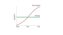
True velocity. Most rodless cylinders are equipped with internal devices to help cushion the load at the end of stroke. But it is important to know the final or impact velocity to determine the cylinder’s cushioning capacity. This differs from average velocity.
For instance, stroking a 24-in. actuator in 1 sec yields an average velocity of 24 in./sec. A reasonable guideline for calculating the final (impact) velocity is that it’s twice the average velocity, or 2 24 = 48 in./sec impact velocity in the example.
Deceleration forces. Given the impact velocity, engineers must then review load position and the resulting moments on the cylinder to determine if shock absorbers or external load-stopping devices are needed. Consider the following example. A cylinder carries a 10-lb. load offset 12 in. from the carrier, and travels at a final velocity of 80 in./sec when it hits shock absorbers at the ends of the cylinder stroke. The load must stop within the shock absorber stroke of 0.50 in. The Mz and equivalent force applied to the cylinder’s load carrier need to be within the cylinder’s rated capacity.
To determine this, first calculate the deceleration rate:
a = vf2/(2s)
= (80 in./sec)2/(2 0.50 in.)
= 6,400 in./sec2
where:
a is the deceleration rate, in./sec2,
s is shock stroke, in., and
vf is final velocity, in./sec.
Then calculate deceleration force, Fd, from:
Fd = (a P)/g
= (6,400 in./sec2 10 lb.)/(386.4 in./ sec2)
= 165.6 lb.
where:
Fd is the deceleration force, lbf,
g is the gravitational constant, 386.4 in./sec2, and
P is the load.
Finally, the moment load created during stopping is:
Mz = Fd L = 165.6 lb. 12 in. = 1987.2 lb.-in.
where
Mz is moment about Z axis, and
L is distance of load from the cylinder’s load carrying device.
Compare this value to the actuator’s rated load capacity to ensure proper sizing. If the moments created during deceleration are more than the actuator’s load capacity, you have two choices: Select a cylinder with a larger moment rating; or put shock absorbers at the load’s center of gravity. The latter theoretically eliminates all moments on the carrier during deceleration. If final velocity cannot be accurately determined, consider using limit switches with valve deceleration circuits, in addition to shock absorbers.
Additional Factors
Motion lag. It is important to understand how other forces and losses affect the total force needed to generate the desired motion. The total force is the sum of acceleration force, frictional forces, and the breakaway force. Here’s a closer look at each:
- Breakaway force. It always takes a certain amount of force to move a rodless cylinder even with no load attached. This force is referred to as breakaway force. When reviewing performance data for a cylinder, be sure to account for breakaway force in the calculations. In pneumatic applications, it is best to have excess force available to ensure reasonable acceleration.
- Acceleration force. The force needed to accelerate a load is typically larger than the force needed to keep it in motion. When selecting an actuator, the cylinder’s breakaway force and the load’s frictional drag must be added to acceleration force requirements.
- Friction forces. Two materials sliding across each other generate frictional force in the opposite direction of the motion. The amount is defined by a numeric value called the coefficient of friction, μ, which varies by material and the type of friction (sliding or rolling). Engineering reference tables list coefficient values for a variety of materials.
For horizontal applications, the force required to overcome the friction is:
Ff = μ W
where:
Ff is the frictional force, lbf, and
W = weight of the load, lb.
Mounting orientation. Vertically mounting the cylinder brings additional force, load, and air considerations. Vertical cylinders need to overcome the force of gravity before they can accelerate loads upward, which means they must produce more force than horizontal cylinders. In vertical applications, it is best to select cylinders with twice the force needed for adequate acceleration.
In addition, some types of pneumatic rodless actuators may leak air. If the actuator needs to hold a load vertically for any length of time, the air leak can affect how well that position is maintained. In certain circumstances, holding devices such as a brakes or external guidance systems may be required to safely control the load. Keep in mind that vertical applications with externally guided loads still see moment loads due to gravity. For example, a 50-lb. load with a bracket arm 12 in. from the actuator’s load carrier would be subjected to a 600 lb.-in. moment load.
Environmental considerations. Failing to factor in environmental considerations can lead to catastrophic results. Extreme heat or cold, external abrasives, dirty or wet conditions, caustic fluids, and air quality are just a few of the conditions that affect cylinder life. Frictional wear (abrasive, pitting, adhesive, and corrosive) due to particulates or fluids hitting the cylinder can cause premature wear or failure and increase maintenance.
Most manufacturers specify cylinder performance based on normal operating conditions. If the cylinder must operate in adverse environments, it is best to discuss this with the manufacturer to determine if the cylinder can deliver the expected performance.
This article was written and contributed by Tolomatic.
This article is part of Power & Motion's Fundamentals of Fluid Power: Pneumatics ebook; download the full guide to learn about the latest technologies and design methods for developing modern pneumatic systems.
