This file type includes high resolution graphics and schematics when applicable.
The Americans with Disabilities Act states that public transit authority and school district vehicles must be accessible to people with disabilities. Original equipment manufacturers (OEMs) believe kneeling (lowering and raising of the bus’s floor) could be key to meeting that mandate, so much so that they’re now equipping their vehicles with kneeling capabilities, making it easier for passengers to climb aboard.
Since this mandate went into effect for 100% of all fleets a couple of years ago, these past winters have taught OEMs the importance of specifying control modules for kneeling functions. Not only must they be durable, compact, and lightweight, but they have to withstand harsh winters like this past one.
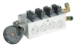
The control modules are tasked with deflating flexible air actuators on demand, quickly lowering a bus to ease passenger entry, and subsequently inflating the actuator at a similar pace, enabling the bus to resume its scheduled route. Control modules are designed for OEM installation on new vehicles, as well as for retrofitting on older vehicles.
The challenges faced by fleet owners this past winter have made these modules the centerpiece of accessible vehicle equipment. Buses in major cities make hundreds of stops per day, and the actuators must lower and raise the bus floor at every stop. Throw in the record snowfalls and extended below-freezing temperatures, and a strong potential exists for schedule delays and added difficulty for passengers entering and exiting the buses. When circumstances are severe enough to cause control-module failure, physical limitations may prevent some passengers from being able or allowed to board a bus for their own protection.
What can go wrong
The two most common failure modes for control modules are lifecycle failures and leakage failures. A lifecycle failure, the most extreme failure mode, occurs when the module does not perform as required. This can be caused by solenoid failure, poppets or spools sticking, or a broken spring. Many transit authorities and fleets will disable the vehicle’s kneeling function as a result of continual inconsistent performance.
In the case of leakage failure, the module continues to perform, but the leaking compressed air wastes energy. This is considered a secondary failure mode because it’s less severe. Leakage failures can result in excessive noise either at the point of the leak, or quite often from the air compressor running almost constantly to maintain system pressure. The noise is certainly an issue for the driver and passengers. More importantly, though, the load placed on the engine by the extended operation of the compressor wastes fuel and increases maintenance costs. Chronic leakage failures can often escalate to more severe lifecycle failures.
Failure causes
Extreme temperature, contamination (both dirt and moisture), and vibration are the most common causes of failure. Bus manufacturers and fleet owners in many parts of the country know they must prepare their equipment for operation within a wide range of temperatures because both high and low temperatures can lead to failure. High temperatures may cause seals to soften and wear too quickly. Solenoids failures can also occur from overheating if the control module is exposed to temperatures exceeding 100°C.
Leakage and lifecycle failures from low temperatures are much more common. Kneeling systems must be able to meet the industry-standard requirement of performance at –40°F. When temperatures approach or exceed this extreme, seals begin to harden and stick, preventing valves from shifting. Hardened seals are also more susceptible to being cut as the valve operates, creating leakage through the seal. Eventually, the damage will worsen to the point of causing a lifecycle failure. Seal shrinkage due to extreme cold can also prevent the valve from sealing properly, again resulting in a leakage failure.
If a pneumatic kneeling system does not incorporate an air dryer, or an existing dryer is not properly maintained, moisture entrained in the compressed air can cause lifecycle failures, too. In addition, since water in the air freezes at temperatures below 32°F (0°C), valves within the control module may not be able to shift.
Regardless of a module’s ability to operate in extreme temperatures, an effective system must be provided and maintained to dry the system’s compressed air. If moisture is not removed from compressed air, it will condense as liquid in the lines, causing line and component damage upon freezing. Even without freezing, water in the compressed air stream may wash away needed lubricants in cylinders and valves, triggering equipment malfunctions and premature component failure.
Although not as severe a factor as extreme temperatures, contamination is another leading source of kneeling control-module failure on buses. Contamination from weather and environmental conditions causes damage and potential failure to both the external and internal components of a control module. Dirt, dust, water, salt, and other debris can eventually lead to extensive damage and leakage failures. Therefore, it’s absolutely critical to design a system that will protect the module against these harsh elements.
Internal corrosion is usually caused by contamination from water or degraded oil from the system’s compressor. Such contamination can often produce more severe lifecycle failures. Oil from components of the air system may also damage the module as it reacts with other internal components. Seals suffer the most significant damage because chemical reactions can impair seals significantly, thus reducing the life of the entire control module.
Finally, if not designed properly into a product, fasteners, springs, connectors, fittings, and other components can become loose or suffer premature fatigue failure due to forces generated from shock and vibration.
The sum of a module’s parts
Several design and construction characteristics directly contribute to the ability of buses to kneel and rise through the toughest conditions. A single-piece anodized body should be at the core of a control module’s design. An aluminum body provides light weight and corrosion resistance, and an anodized finish adds further protection from corrosion and wear.
A single-body design also offers the flexibility to build three- or four-station modules from identical components. On top of that, a one-block design has a single bolt-hole pattern, which simplifies installation and replacement. Ultimately, it reduces parts and labor cost in the field due to fewer components and connections. Fewer connections also mean fewer leak paths than with multiple assemblies.
The valve design strongly influences the life and performance of the control module. The poppet assembly is also the most affected by temperature, contamination, and vibration, and thus the most vulnerable component of the module. An over-molded poppet valve design suits harsh environments better than a spool design. And, of course, a valve design with fewer components reduce the risk of failure.
Low-temperature dynamic O-rings, used in conjunction with low-temperature grease, allow a module to operate at harsh transportation environments. Two O-rings combined with a precision-ground poppet ensures that the module will withstand the temperature extremes and corrosive environments typically encountered by city buses.
Exhaust protectors act similar to a check valve—they permit unrestricted exhaust air flow while preventing the ingression of ambient air. This blocks external contaminants and moisture from entering the module through the exhaust port.
This file type includes high resolution graphics and schematics when applicable.
The solenoid and pilot operator should both be temperature-rated to –40°F to +158°F (–40 to +70°C) and have voltage characteristics of ±30% of rated voltages. Additionally, to ensure the ruggedness of the pilot operators, they should have a maximum pressure rating of 232 psig (16 bar).
Paxton Augustine is Product Marketing Manager at Parker Hannifin’s Pneumatic Div., Richland, Mich. For more information, call (269) 629-5000 or visit www.parker.com/pneumatic.


