This file type includes high resolution graphics and schematics when applicapable.
Programmable logic controllers (PLCs) are used widely in machine control. However, users should be aware of the limitations associated with them. Consider a position control system where the PLC and associated sensors are used in a programmable limit switch operation. The aim is to start deceleration before the desired stopping point is reached in the hopes that the targeted stopping point is reached with precision. Such control methods take advantage of proportional valves and the deceleration control electronic modules often built into them. However, turning acceleration and deceleration control on and off using a PLC can cause errors in the final stopping position of a cylinder.
The error is caused by the scan-time delay in the digital controller, and it is directly proportional to the speed at the instant that the deceleration decision is made. To reduce this error, many open-loop motion controllers decelerate the system to a creep speed to approach the target position slowly. Thus, positioning error is made at creep speed instead of at maximum speed, so the ultimate position will be acquired more accurately.
A familiar example of this control technique is demonstrated in self-serve gas stations when prepaying a specific dollar amount for fuel. If you tell the clerk that you want only $40 worth of gasoline, the fuel will flow at a maximum rate until a volume equal to, say, $39.80 worth of gasoline has been dispensed. At this point, flow quickly drops to barely a trickle, and gasoline dispenses at perhaps 4¢/sec. This makes it easy for the pump control to terminate the transaction precisely at $40.
The disadvantage of using a creep plateau in PLC motion control is that it either extends the cycle time or it requires a higher maximum speed, VSS, for the system to maintain the total machine cycle distance. A higher VSS necessitates higher acceleration and deceleration rates, which may induce cavitation in the actuator. Higher maximum speed also requires a larger control valve or higher supply pressure.
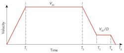
Steeper slopes are also rich in high-frequency components, which can induce springiness from hydromechanical resonance, giving an undesirable bounce at the end of the cycle. Nonetheless, if the alternative is unacceptable positioning error, using a creep speed plateau, Figure 1, is usually the positioning strategy of choice in the bang-bang control systems under discussion.
In practice, T1 is usually known; however, other times it must be tuned at commissioning time based upon a perceived optimal performance. That optimal performance is a compromise between cycle time and final positioning ability. If random factors affect the T1 decision point when the system is finally tuned, then the tuner will always readjust the system to create the longest possible creep time from T3 to T4. This is because when the PLC sample time occurs immediately following the acquisition of the ideal deceleration timing point, and if T2 is timed to minimize the creep time, then the PLC sample surely will occur immediately before the ideal deceleration timing point during a subsequent cycle. Ultimately, the target will be overshot by an amount equal to the product of the sample interval and the slew (highest attainable) speed.
Of course, if the deceleration timing point is one interval late, then the creep speed time interval must be commensurately reduced to attain the final position. That, after all, is the purpose of the control system. For now, let’s evaluate the idealized profile of Figure 1.
Examining an example
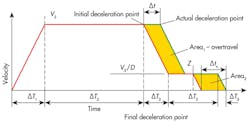
If the system designer can make a reasonable estimate of the several times in Figure 1, and if there is a final positioning target, then the slew speed can be found to achieve all times and the final stopping position from Equation 1. Note that xTis the final, or target position, and the creep speed is the maximum speed, Vs, divided by the slowdown ratio, D. Now, because there is a Vs (Figure 2) in every term of Equation 1, then the slew speed can be found using Equation 2.
Returning to the problem of determining the time length of the creep-speed plateau, Figure 2, will be helpful in explaining the point. This figure shows the individual time intervals, rather than the elapsed times of (Figure 1). To illustrate the effect of missing the initial deceleration point, consider that the PLC has an iteration time of ∆t. The actual deceleration point, then, will be delayed by ∆t. It is important to recognize that the extra travel that occurs due to the delayed deceleration decision is indicated by shaded Area 1. Because a transducer monitors the actual actuator position, a final, but far shortened deceleration point, Z, will ensue. Therefore, final deceleration will take place ∆tx sec earlier than the “planned” final deceleration point.
At this time, please note that Area 2 must equal Area 1, and that the machine, by its design, will do this automatically. We need to gain knowledge of ∆tx, because its value will dictate the minimum requirements of the planned creep speed plateau.
A knowledge of physics and calculus tells us that:
xT = ∆T1VS/2 + ∆T2VS + ∆T3(VS – VS/D)/2 + VS∆T3/D + VS∆T4/D + VS∆T5/2D (1)
VS = xT/[∆T1/2 + ∆T2 + ∆T3(1 – 1/D)/2 + ∆T3/D + ∆T4/D + ∆T5/2D] (2)
Area 1 = Area 2 (3)
The area of a trapezoid is its vertical height times its horizontal base, so:
∆t[VS – (VS/D)] = (VS/D) ∆tx (4)
Therefore:
∆tx = (D–1) ∆t (5)
This means that ∆tx is the minimum creep plateau that must be used to ensure that missing of the initial deceleration point by one iteration interval does not result in an overtravel of the final deceleration point. Note that it relates directly to the iteration interval of the PLC and the slowdown ratio.
To be on the safe side, the design target for the creep plateau should be about 20% greater than the value in Equation 5. But the bottom line is this: The machine now spends more time at low speed. This means that either maximum speed must be increased — requiring more expensive hardware — or machine throughput and productivity must be sacrificed due to a longer cycle time.


