Spool-valve transition conditions
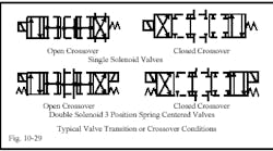
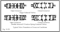
When a spool valve shifts from one flow condition to another, it can pass through different flow conditions than those indicated by straight or crossing arrows in the symbol. These transition or crossover conditions are unimportant in most circuits, but can cause shock, drifting, or cylinder regeneration under certain circumstances. Figure 10-29 shows typical transition conditions for open- and closed-center, 2- and 3-position valves. For transition conditions of other valve center types, see Chapter 4.
An example of how an open transition or crossover can eliminate shock is the case of a fast-moving actuator that must reverse direction before the end of its stroke. With a closed-crossover valve in this circuit, all flow to and from the actuator is blocked for a brief period as the spool shifts from extend to retract. The pump side of the valve always has a relief valve (or a pressure-compensated pump) to protect it from over pressure. However, the actuator side has no protection of any kind. When flow from the extending actuator is blocked, pressure can build to levels well above the pressure ratings of pipes, seals, and hardware. This pressure spike is very brief, but it happens every cycle -- and soon shows up as cracked fittings, blown hoses, leaking seals, or broken parts. Changing to an open-crossover spool in this application would connect the impending spike to the relief valve or pressure-compensated pump. There is still a pressure spike but its intensity is now below the damage level of the components.
An example of where a closed transition spool helps is when a vertical cylinder with a heavy platen must be reversed in mid stroke. With an open transition, the cylinder will continue its forward travel after the valve receives the reverse signal. With a closed transition, the cylinder will stop almost immediately and start reversing shortly thereafter. Also, when the platen must retract from a stop position, such as during set up, it can drop before being powered up with an open-crossover valve in the circuit.
Crossover problems usually show up when a 3-position valve shifts to or from center condition. Cylinders may move in the opposite direction or move when signaled to stop for no apparent reason. Most suppliers show crossover flow in their catalog so check it out if the problem is an unusual movement.
Mounting pneumatic valves
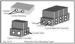
Pneumatic valves can be line-, subplate-, or manifold-mounted. Inline or bar-type manifolds make it convenient to stack valves with a common inlet and/or exhaust. Pneumatic circuits seldom, if ever, require custom manifolds as hydraulic circuits do. The graphics in Figure 10-30 depict some pneumatic-valve mounting styles. In-line mounting types have the whole valve assembly in a body with ports out the sides. This style is usually less expensive, but is more trouble if it has to be replaced.
The typical pneumatic subplate assembly is often a subplate with end covers bolted to it. Fasteners hold the parts together and molded seals eliminate leaks. Valves with seals mount to the subplate and all piping connects to it. Some manufacturers have wiring troughs in the subplate and use plug-in connectors on solenoid-operated valves.
The typical pneumatic manifold assembly consists of two or more subplates connected to make a valve stack with a common inlet and exhaust. These assemblies eliminate many connections and make valve installation replacement easy. These units also are available with wiring troughs and plug-in valves for solenoid operation. Most air valves use unique mountings and port arrangements that are not inter-changeable. However, there is an ISO standard subplate mounting that several companies offer. The valves match each other’s mounting patterns but otherwise do not have interchangeable parts. This assembly is physically large and thus more expensive, but it makes it easy to combine valves from several suppliers.
Mounting hydraulic valves
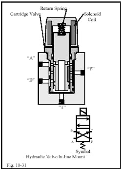
In-line and subplate-mounted hydraulic valves are common. However, most in-line valves are screw-in cartridge type with aluminum or steel bodies. Figure 10-31 shows an example of an in-line cartridge valve. (This valve also could be screwed into the custom manifolds discussed later.)
Screw-in cartridge valves perform all directional and flow control, relief, sequence, counterbalance and reducing functions -- the same as in-line and subplate valves. Only their physical makeup is different. They normally handle flows less than 40 gpm, but some manufacturers offer sizes with up to 120-gpm capacity.
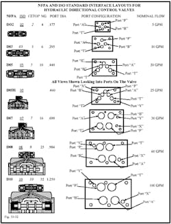
There are worldwide interface standards for subplate-mounted hydraulic directional control valves. The information in Figure 10-32 shows port and bolt locations and relative sizes for all standard sizes. The figure also lists the numbering systems for U. S. National Fluid Power Association (NFPA), worldwide International Standards Organization (ISO), European Committee for Oilhydraulics and Pneumatic Control (CETOP), and the NG part of the German DIN Standard, which relates only to port size in metrics. (Actually, the NG port size can be for any type valve.)
Interface standards cover both size and location for ports and bolts. A directional valve from any country or manufacturer using this standard is interchangeable with all other valves of the same size. The only difference should be whether the bolts have SAE or metric threads.
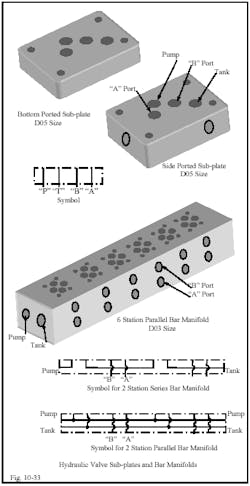
Figure 10-33 depicts typical subplate and bar-manifold mounting arrangements for subplate-mounted directional control valves. Subplates mount a single valve and are used in simple single-cylinder applications. They come in bottom- and side-ported models for piping convenience. Some side-ported models have bottom ports as well.
Subplates can be used for multi-cylinder circuits but require a lot of pipe connections that can restrict flow and may be potential leakage points. Many multi-cylinder circuits work well with the bar manifold shown in Figure 10-33.
Subplates are available for all the valves listed in Figure 10-34. Porting for larger valves usually involves SAE flanges on the valve body. When they have subplate mounts, a special subplate must be made or they are mounted on a custom manifold.
Bar manifolds come with series and parallel porting related to pump and tank connections. Series manifolds usually are limited to three stations or three valves maximum, while parallel manifolds can have as many as 16 stations.
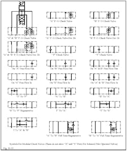
When circuits are not too complex, bar manifolds and modular accessory valves can eliminate most pipe connections and put everything in one location. Symbols for these modular valves are shown for most of the types available. They are always at the end of a section for a particular accessory valve.
Bar manifolds are only offered in sizes D02, D03, D05, D05H, D07 and D08. Size D10 valves use subplates or specially made bar manifolds, or are mounted on a custom manifold.
Custom manifolds
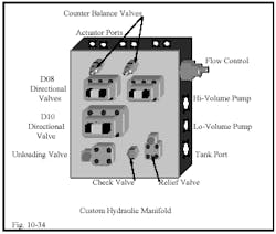
Figure 10-34 depicts a custom manifold that can eliminate many plumbing connections and make valve replacement easy. Such manifolds are usually more expensive than simple plumbing, but can save many times the extra first cost by minimizing fluid loss through leakage and the cost of cleanup.
A number of companies specialize in designing and building custom manifolds. All they require is a schematic of the circuit with the valves to be included inside chain lines; plus other information such as preferred pipe connection type, connection locations and size, which face or faces to leave clear and manifold material. If there is a preferred mounting arrangement, it should be noted along with mounting bolt locations.
Remember: manifolds are difficult to modify, so they should only be applied to proven working circuits. If in doubt about the viability of a new design, work out the bugs in standard piping before buying a manifold.
Most check valve functions are available as modular or sandwich valves that mount between the directional control valve and subplate. Figure 10-35 shows most of the common configurations presently offered by fluid power suppliers. These modules are usually available in all valve port sizes up to D08 (3/4 in.).
