Hydraulicspneumatics 807 Belart Red P

Indicators let you “eyeball” airflow

Sept. 11, 2013
When troubleshooting or monitoring the status of a low-pressure pneumatically powered or controlled machine — such as medical equipment or air-logic circuits — it can be next to impossible to determine if air is flowing through a particular line, even if clear tubing is being used. You could provide a flowmeter for each critical line, but that can get expensive.
When troubleshooting or monitoring the status of a low-pressure pneumatically powered or controlled machine — such as medical equipment or air-logic circuits — it can be next to impossible to determine if air is flowing through a particular line, even if clear tubing is being used. You could provide a flowmeter for each critical line, but that can get expensive. You could take the low-tech route and pinch the line, but that will only indicate a line is pressurized — you still don’t know if flow is actually occurring. Some might try loosening a line to let air leak out, but this unsafe practice holds potential dangers or could cause a machine
malfunction.

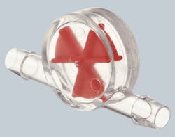
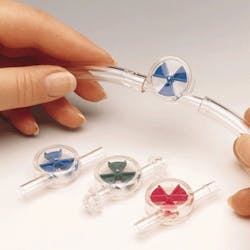
Bel-Art Products Inc., Wayne, N.  J., offers an effective and economical solution: a series of in-line indicators that clearly shows users when differential pressure (therefore, flow) exists. Mounted in any position, the transparent-polystyrene indicator contains a wheel marked with blue, red, or green triangles. Whenever there is a change of pressure in the line, the wheel spins rapidly, yielding the appearance of a solid color. Each color corresponds to the indicator size and flow rating. Blue models fit and 1/4-in. tube and indicate flows from 0.5 to 10 lpm. Red models fit 1/4 and 5/16-in. tube and indicate flows from 0.5 to 10 lpm. Green models fit 5/16 to 1/2-in. tube. All three indicate flows from 0.5 to 10 lpm and are rated for pressure to 10 psig. Whenever pressure changes at either end of the tubing n the line, the wheel spins, yielding the appearance of a solid color.

For more information, call Bel-Art Products at (800) 423-5278 or visit bit.ly/17LilVD.
Continue Reading

BOOK 2, CHAPTER 12: Fluid Motor Circuits

March 18, 2009
Table of Contents

Motor leakage variations

Oct. 18, 2006
affect low-speed performance

Sponsored Recommendations

7 Key Considerations for Selecting a Medical Pump

Feb. 6, 2024
Newcomers to medical device design may think pressure and flow rate are sufficient parameters whenselecting a pump. While this may be true in some industrial applications, medical...

How Variable Volume Pumps Work

Feb. 6, 2024
Variable volume pumps, also known as precision dispense pumps, are a positive displacement pump that operates by retracting a piston to aspirate a fluid and then extending the...

What is a Check Valve and How Does it Work?

Feb. 6, 2024
Acheck valve, a non-return or one-way valve, is a mechanical device that allows a gas or liquid to flow freely in one direction while preventing reverse flow in the opposite ...

The Difference Between Calibrated Orifices and Holes

Feb. 6, 2024
Engineers tasked with managing fluid flow talk about both holes and calibrated orifices, but they are two distinct entities. A hole can be any opening, but a calibrated orifice...