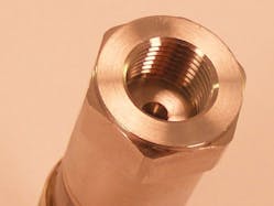
Hydraulic systems often incorporate pressure transducers to monitor for safety as well as optimize system performance using closed-loop feedback. For instance, pressure transducers within a hydraulic control system can ensure that a heavy load won’t tip over a forklift, monitor trash-compactor performance, control hydraulic pumps on oil rigs, or ensure accurate performance of aircraft landing gear. Although hydraulic applications vary greatly in terms of safety and precision, the same principles apply to protect pressure transducers against hydraulic overpressure events, fatigue, and environmental conditions.
Pressure transducers can be specified to work under steady-state or pulsation conditions. A typical hydraulic system, whether stationary or mobile, operates from 0 to 500 psi (35 bar) to 10,000 psi (700 bar). Most pressure transducers are specified with a proof pressure or overpressure specification; therefore, transducers should perform within specification at two times the rated pressure (such as 6,000 psi for a 3,000-psi pressure transducer).
For some benign applications, pressure transducers can be dropped into a hydraulic system and operate accurately without modification. In other cases, pressure events will far exceed the transducer’s normal operating pressure limits. For example, if a local hardware store’s hydraulic trash compactor has a block of concrete stuck under the lip of the moving body, pressure pulsations sent to the pressure transducer may extend far beyond the hydraulic system’s normal operating pressure. Such a pressure event can be five times the transducer’s rated pressure, leading to failures in standard transducers. In another scenario, if a forklift operator picks up a full load on the forks and lowers it to the ground, the forks could bottom out and send a pressure spike through the hydraulic lines. When the spike reaches the transducer, it’s likely to exceed rated pressures, again damaging transducer failure.
Fast-acting valves also create pressure transients. For instance, the pressure event from a transducer located close to an opening and closing valve will create surges downstream from the valve. Pressure surges can cause a pressure transducer to fail by deforming the diaphragm or breaking the sensing elements above it. Possible ramifications include cracked ceramic diaphragms, shifting of oil-filled units, and wire bonds lifting off of strain gauges.
Icing also produces situations similar to pressure transients. If water becomes trapped within an unpressurized hydraulic system, it can freeze in cold ambient conditions and generate a simulated pressure of 1,500 psi. A pressure transducer doesn’t recognize the difference between pressure and ice, and will fail after long-term exposure to these conditions.
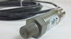
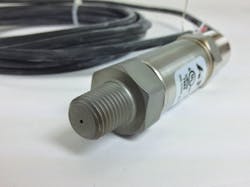
One way to protect pressure transducers against pressure spikes or rapid pressure changes is to add a restrictor plug (snubber) inside or outside of the process connection. The snubber serves to dampen spikes and surges on the pressure transducer, Figure 1. Internal snubbers reduce the transmitter’s overall height, whereas external snubbers facilitate cleaning of hydraulic systems, which are prone to collect contamination.
Another possibility is to increase the pressure transducer’s proof pressure. Advances in signal processing now enable manufacturers to use thicker diaphragms when manufacturing the internal body of units, which boosts proof pressure for the same measurement range with minimal losses in performance. Rather than lose resolution by increasing the device’s measurement range, the transducer manufacturer can calibrate the same pressure range with a higher proof pressure.
The proof-pressure solution is ideal for icing issues. With snubbers, it’s possible to trap water within the transducer. On the other hand, an open cavity with higher proof pressure than the freezing-induced maximum pressure exerted on the diaphragm would be more likely to survive.
With the exception of a flush-diaphragm transducer, all pressure transducers have a cavity that transmits fluid pressure to a diaphragm. A snubber can be installed inside that cavity with a smaller inside diameter to dampen a pressure spike as it travels through the hydraulic to the transducer. Instead of the pressure wave shocking the diaphragm, it hits the face of the snubber and slowly feeds the liquid through the hole.
Technology Considerations
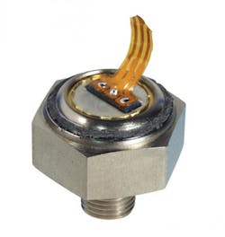
The type of technology chosen for hydraulic pressure transducers depends heavily on the nature of the application and operating pressures. For example, a pressure transducer with a capacitive or thick-film ceramic diaphragm, Figure 2, is typically specified up to 400 bar with 1½ times of rated pressure for steady-state applications. This transducer will fail in dynamic and pulsation applications due to fatigue, because ceramics perform poorly under tension.
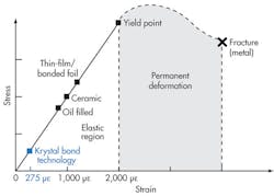
Similarly, thin-film-based technologies operating under high strain levels will fail due to zero shifting. Moreover, as the pressure range increases, the proof pressure drops off rapidly due to the strain level approaching the yield point of the diaphragm material. Figure 3 shows typical strain values for pressure-sensing technologies. Krystal Bond technology offers a one-piece design and low operating strain, which are ideal for demanding hydraulic applications where pressure spikes and cavitation are of main concern.
Key Components For High Pressure
Pressure ports and the mechanical interface are crucial parts of the pressure transducer when it comes to safe operation for hydraulic systems pressurized to 45,000 psi (3,000 bar). Pressure ranges up to 7,500 psi can use ¼-in. tapered ports such as National Pipe Thread (NPT) or British Standard Pipe Taper (BSPT). Beyond this pressure range, a metal-to-metal seal must be employed in high cyclic or dynamic operation, Figure 4.
Straight threads such as ¼-in. British Standard Pipe Parallel (BSPP), G¼, 7⁄/16-20 UNF, and 9⁄/16-218 UNF use an O-ring to seal against the fluid. These O-rings are good for static operations up to 1,000 bar. However, under dynamic and high-vibration conditions, they must be derated to 400 bar as suggested by SAE. Otherwise, the fitting will loosen, and fluid will leak.
Greg Montrose is marketing manager and Karmjit Sidhu is vice president at American Sensor Technologies, Mount Olive, N. J. For more information, visit www.astsensors.com or call (973) 448-1901.
