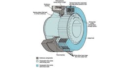
One of the many attributes of versatile fluid power systems is the ability to control speed and torque delivered to a load from a prime mover. But hydraulic system designers often overlook clutches as an alternative.
Installing a clutch between a system’s prime mover and load provides an efficient means of placing the system on standby. But saving energy by unloading an entire power system is just one important function of clutches. They can also reduce system cost by tapping into a pressurized hydraulic system to engage or disengage many rotating components. They do this with negligible drain on a hydraulic power system because they require high pressure but very low fluid volume for actuation.
For example, a mine machine might use separate motors and controls for it’s the cutter head, gathering arms, conveyor, and a separate drive system for propulsion. By incorporating clutches into each of these drives, any particular function can be engaged or disengaged independently from one main power source.
Available types
In addition to fluid power, clutches also rely on mechanical, electrical, and electromechanical methods of actuation. These other types, however, will not be discussed beyond their general characteristics.
Mechanically actuated clutches are simple, inexpensive, and provide the operator with a good feel of engagement. However, actuation usually depends on manual positioning of levers and linkages, thereby limiting sensitivity of control, response time, and frequency of engagement.
Electrical clutches include such designs as magnetic particle and eddy current. These clutches use voltage control to achieve partial engagement of input and output shaft speed so the clutch can control speed and torque. Unlike fluid power clutches, electrical clutches consume power continuously while engaged.
Electromechanical clutches use a solenoid for engagement and springs for disengagement. This allows very rapid cycling rates, but, again, they can consume substantial electrical power. They also generate heat in their coils during periods of engagement. Furthermore, large solenoids must be used to accommodate heavy loads. Solenoid size and allowable voltage in controls thus limits the size of these clutches.
Fluid power clutches
Hydraulically and pneumatically actuated clutches, on the other hand, generally use fluid (oil or air) pressure to engage a load and springs to disengage. Alternative designs may use springs to keep loads engaged and fluid pressure to disengage. Because the pressure fluid is static, very little power is consumed once the clutch is engaged.
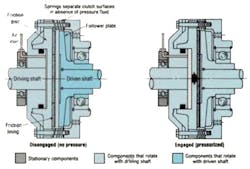
Disc types are the most widely applied fluid-actuated clutches. A single plate, air-actuated design is shown in Figure 1. Pressurized air enters the clutch and pushes a driving pate against a driven pate. A high-friction-coefficient material, bonded to the driving plate, transmits torque from driving plate to driven when the clutch is engaged.
The friction disc lining usually is of paper, elastomeric, graphitic, or sintered material, predicated by the application. Consideration is given to friction characteristics, elevated operating temperature, heat dissipation, and other variables. The driven plate usually is of high-carbon steel to resist distortion under hi-temperature conditions.
But a clutch’s load capacity is limited by the area of the friction disc contacting the driven plate. Because the friction lining has a finite coefficient of friction, load capacity can be increased only by increasing the lining’s contact surface area for the engagement force. For this reason, single-dic air clutches have limited capacity because operating pressure usually does not exceed 110 psi, and increasing the lining area means making the clutch larger and more massive.
Increasing capacity
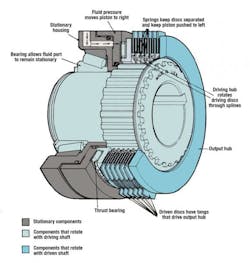
Multiple disc clutches offer one solution. By engaging many friction discs against many driven discs, capacity increases dramatically with only modest increases in clutch size and weight. In this design, Figure 2, fluid pressure acts on a piston that pushes driving and driven discs together. Splines, lgus, or other geometries allow discs to move axially to contact each other and transmit torque. A drive cup surrounds the OD of driven discs and serves as the output member. Release springs between driving discs keep discs separated-and the clutch disengaged-in the absence of pressure acting on the piston.
Moreover, by actuating the clutch with hydraulic fluid instead of air, much higher actuation forces can be generated because higher pressures—often to 500 psi—are available. Combining these two features means that a multiple-disc hydraulic clutch can transmit much higher torque in a smaller envelope than pneumatic clutches can.
However, the rotting cylinder design requires pressurizing the clutch through axial holes drilled in its mounting shaft. These holes must be supplied with fluid through a rotary seal at the end of the rotating shaft. If two or three clutches are mounted on the same shaft, three oil supply lines must be drilled and a triple-passage rotary seal provided.
Drum clutches
Though not as extensively used as disc clutches, drum clutches usually are applied in heavy-duty equipment, especially where large shaft diameters are involved. Petroleum, construction, mining, marine, and metal processing applications are typical.
The clutch’s outer drum attaches to a flywheel, coupling half, or other driving element. This rigid outer drum contains a rubber-actuating ring that resembles an inner tube. Friction pads are attached around the actuating ring’s ID, with the driven shaft located inside the circle formed by the friction pads.
To engage the clutch, air, typically at 75 to 100 psi, enters the actuating ring through the outer drum. The pressure expands the actuating ring, causing its ID to contract. This action presses the friction pads against the driven shaft and engages the driving shaft with the driven.
Drum-type clutches provide cushioned engagement because power is transmitted through the resilient actuating ring. Expansion of the ring compensates for friction pad wear, so the clutch self-adjusts. However, these clutches take up much more space than multiple-disc types, especially when they’re used to engage and disengage two collinear shafts. They’re also heavy and limited to relatively low speeds because high centrifugal force can overcome air pressure force to cause slip at high speeds.
Clutch selection
Basic information that must be gathered before selecting a clutch for any application includes, of course, required torque and speed. But two other parameters take on special importance in conjunction with proper clutch specification: system inertia and duty cycle.
The system inertia includes the individual inertias of all rotating components that the clutch will have to start rotating: the load, shafts, pulleys, gears, sprockets, bearings, couplings, etc.
System inertia is important because a clutch may be undersized even though it has enough torsional capacity to transmit required power. For example, a high-inertia load—such as a large gear train on a coal conveyor—could overheat a clutch if a long period of slip occurs when attempting to accelerate the load up to operating speed.
Duty cycle, the number of star/stop cycles per minute, also plays an important role. When the clutch engages, its mating surfaces slip—which generates heat—while the load accelerates to operating speed. Once this occurs, the clutch must dissipate the built-up heat. If not enough time occurs between engagements to dissipate the heat, it can build up to temperatures that reduce life of the clutch.
This concept of system inertia and duty cycle is summarized in on calculation, thermal horsepower. Clutch manufacturers can provide users with thermal horsepower ratings that serve as a useful guideline for proper clutch selection.
To extend service life, a clutch’s thermal horsepower rating should exceed the application’s calculated thermal horsepower. Low system inertia and engagement frequency generally yield a long service life for clutch frictions surfaces because heat can be dissipated soon after it is generated. Sometimes a heat exchanger must be used to help dissipate the heat that builds up and transfers the oil.
Designers may attempt to oversize a clutch in hopes of avoiding the overheating and premature failure that can occur with too small a clutch. But too large a clutch may engage the load too suddenly; causing shock loading that can damage equipment. The clutch should be carefully sized to provide a soft engagement through controlled slip.
The need for controlled slip introduces another advantage of fluid power clutches. If a clutch is oversized, pressurized fluid can be introduced through a flow control valve will engage the clutch gradually to provide a soft start, even if the clutch is oversized.
For more information, call Logn Clutch Corp., Cleveland, at (440) 808-4258, or visit loganclutch.com.


