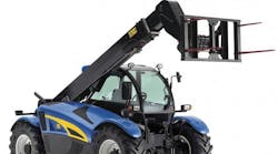
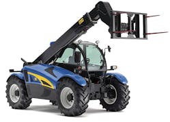
Depending on the attachment mounted to the end of its boom, the telescopic handler (telehandler) is used as an all-terrain forklift, crane, aerial work platform, or even an excavator. Its strength and agility have made it essential for most large construction projects. More recently, it has gained a foothold in materials handling. A pair of pallet forks is the most common attachment for a telehandler, and the most common application is moving loads to and from places inaccessible to a conventional forklift. For example, telehandlers can remove palletized material from a trailer and place it on rooftops. This application would otherwise require a crane, which often is not practical or can be too time-consuming.
However, with skid-steer loader attachments and hydraulic tools readily available, machines are usually required to be much more than just an extended reach forklift. Even though telehandlers are being used with an evergrowing list of attachments and accessories, their hydraulic duty cycle is still relatively light. The telehandler’s versatility has resulted, in large part, from increased functionality of hydraulic valves that control the direction, flow, and pressure of oil to cylinders, motors, and other actuators. Functions typically driven and operated by hydraulics in telehandlers include:
- steering and brakes,
- boom lift and tilt,
- boom and tilt load holding,
- auxiliary attachment controls, and
- cooling fan drive on larger systems.
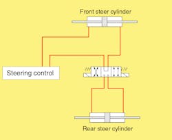
Steering – Usually this is a steering control unit on a priority flow control circuit. Typically a three-position,-four way valve is used to select between normal, coordinated all wheel, and crab steer modes (see schematic).
Braking – The park brake is typically a spring applied, hydraulically released brake, usually part of the axle assembly. It’s also typical to use a brake valve and the hydraulic system for the service brakes.
Boom extend – This is done with a long double-acting cylinder with counterbalance valves built in. The extension is typically multiplied by a chain mechanism.
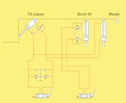
Hoist and forks – This is almost always done with proportionally controlled, double-acting cylinders, with counterbalance valves built into the hoist cylinders. The fork tilt function typically has a “master/slave” circuit that provides fork auto-level as the boom raises or lowers (see schematic).
Maintaining equal movement on cylinders can be accomplished using slave cylinders, in which two or more double-acting cylinders are securely and rigidly connected together at both rod and cap ends and have a common inlet. Each outlet is connected individually to the inlet of oil the main working cylinder. A provision for maintaining a full volume of fluid in the master cylinders must be made.
As oil enters the common inlet of the slave cylinders, the rods will extend together and push fluid from each cylinder equally to operate the main working cylinders. This is a more accurate way of controlling multiple cylinders but requires a more complicated control circuit and much more space.
A simple and economical way of improving the accuracy is to use restrictive style, pressure-compensated flow regulators connected in parallel. There should always be more flow available than the combined settings of the flow regulators. This solution requires the excess flow to go across a relief valve, so it should be used with a pressure compensated pump to prevent wasting excessive energy.
Frame level – This is usually part of the main hydraulic valve, but sometimes is found as an add-on option. Because the machine is typically used on uneven ground, this double-acting cylinder can tilt an axle to level the machine.
Stabilizers – Also called outriggers, stabilizers typically use double-acting cylinders with pilot-operated check valves for load holding. This can be an option, and many machines do not have them.
Auxiliary functions – This broad category can be anything from a tool circuit to a powered fork rotate. It’s just an extra circuit or two, sometimes proportionally controlled and usually an add-on option. The largest flow requirement is the boom lift, but usually the telescope function takes the same flow. Other functions are generally flow limited.
Design trends
A current trend in the hydraulic system of telehandlers uses a single load-sensing axial-piston pump for supplying the system, moving away from the fixed-displacement double gear pump.
The telehandler functions are changing. Although not designed as aerial work platforms, often they are used that way. Therefore, lifting and leveling circuits should be designed for holding people in the air, not just construction material.
On the other hand, the versatility of telehandlers means that an earthmoving attachment may be used at the end of the boom. In this case, the telescopic cylinder circuit and mechanism has to be designed for pull loads as well as to push (lift) them. An example is back-dragging with a bucket attachment.
Furthermore, telescopic cylinders should have all air bled from them. Otherwise, the extension function will tend to chatter. When a master-slave arrangement is used for fork leveling, end-of-stroke conditions must be considered. Excess fluid must be relieved when the fork tilt cylinder bottoms out. This relief function must be sized according to the greatest possible slave oil flow. An externally vented counterbalance valve works well for the fork tilt cylinder, mainly because of the backpressure associated with routing oil back to tank.
Material for this article was provided by Irene Baer, of Bucher Hydraulics GmbH, Klettgau, Germany, and Eaton Hydraulics, Eden Prairie, Minn.
