This file type includes high resolution graphics and schematics when applicable.
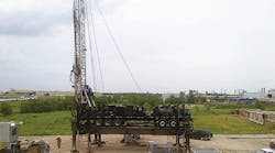
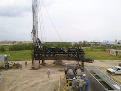
Conventional land-based drilling rigs comprise up to 40 trucks of equipment. Costs can reach $950,000 to take down and set up again in a different location (slot) no matter how close it is. When several wells must to be drilled close by each other, the cost per well can be cut dramatically by moving the drilling rig from slot to slot. Walking rigs were developed for this reason. They can move up to 150 ft at up to 100 ft/hr, rotated, and located over a series of wells as required.
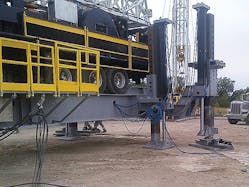
Walking rigs lift the drilling section of the rig and make it mobile. Weighing up to 500,000 lb, and fully laden with racked drill pipe, the rig’s movement has to be carefully monitored and controlled. With sometimes as many as 14 hydraulic cylinders controlling different aspects of the movement, the cylinders’ electronic feedback control system leaves no room for compromise. The cylinders used in the rigs are actually rams—the rod diameter is the same as the piston diameter. By their design, rams are single acting, so fluid pressure extends the cylinder’s rod, and weight of the rig retracts it.
Standing tall and well balanced
Spindletop Production Tools, Gainesville, Texas, designs and builds walking rigs that are fully automatic, requiring no personnel on the rig as it moves. Using an electronic leveling system, the rig is kept level within 0.2 degrees when walking. A programmable logic controller reads an electronic level signal and automatically adjusts stroke of the rams. Position feedback from each ram is produced by linear displacement transducers (LDTs) designed and manufactured by Rota Engineering Ltd. Rota Engineering also makes electrical cabling systems, which allow rapid connection and disconnection of the rig from ancillary services when the rig is to be walked.
Rota’s LDTs give accurate and repeatable position feedback and can be fully imbedded in the rams, with just the electrical connection visible. All electronics are imbedded in the transducer within the ram. Stroke of the lifting rams is closely and continuously monitored to ensure safety by keeping the rig level. The rams stroke up to 9 ft moving at 4 ft/min, with typical pressures to 2,500 psi.
Mark J. Flusche, P. E., petroleum engineer at Spindletop, explained, “Because our rigs are fully automatic, alignment about the wellbore is critical. We use the Rota position sensors in the hydraulic cylinders to adjust the rig for settling during operations. The sensors allow us to make known precise adjustments.”
Because of the likelihood of explosive gases, the monitoring instruments must meet minimum requirements for a Zone 1 rating, where a hazardous atmosphere is likely in normal operation. Rota Engineering supplied intrinsically safe LDTs, which qualify for use in Zone 0, where a hazardous area is continuously present.
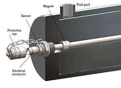
In the drawing shown, a magnet is held and moved by a piston to produce a 4- to 20-mA signal indicative of the ram ‘s stroke position. Rota’s LDTs are absolute devices, so if the electrical supply to the transducer is interrupted, the sensor reads where the ram is the instant power returns, even if the ram had moved during the interruption.
The sheer size of the machinery and the physical working conditions require sensors that are unaffected by vibration or shock. Rota sensors have been independently tested by Wylie Labs, subjecting the sensor to 111 G sine dwell without failure. Flusche added, “We prefer Rota sensors over others because the Rota sensors are far more robust and hold up well in the oilfield environment. Also, they are intrinsically safe and well shielded from noise caused by large ac motors and variable frequency drives.
Quick, reliable connections
Rapid access to the hydraulic ram and its mounting is accommodated by fitting the sensors with Rota’s quick-acting electrical coupling. The coupling is constructed of 316 stainless steel and is designed with interlocks that prevent producing a spark during connection or disconnection. The connectors used are IP-68 rated and can be submerged to 328 ft for 1 hr without leaking. Even when open, they maintain an IP-67 rating.
Rota designed the entire interconnection system, from junction boxes to the quick-acting connectors. Designing the entire interconnection system means that only the correct connectors mate together, which maximizes speed and reliability when working on equipment. The systems are typically used in hazardous land-based and offshore equipment but can also benefit marine environments and other locations where sealing and isolation of electrical signals is critical.
This file type includes high resolution graphics and schematics when applicable.
Submitted by Domhnull McLennan, of Rota Engineering Ltd., Bury, England. For more information, contact Rota Engineering in the US at (260) 749-9631, go to www.rota-eng.com, or visit them at the Offshore Technology Conference booth 2641.
