Download this article as a .PDF
Directional control valves perform three functions: stopping, allowing, and changing the direction of fluid flow. Although international standards describe a valve by its number of ports, it is common in North America to use the term ways, so a 4-way valve is a valve having four ports. Double-acting actuators require 4-way valves because they pressurize and exhaust two pairs of ports independently. Both hydraulic and pneumatic circuits use them, but a 3-position, 4-way valve is more common in hydraulic circuits.
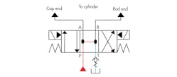
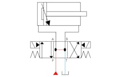
In addition to the normal hookup shown in Fig. 1, many alternative circuit arrangements can be used with 4-way valves to meet specific application requirements. The three sequences show a 4-way valve in action. A double-acting cylinder only needs one 4-way directional valve to extend and retract it.
When a force acts on the rod, flow controls or a counterbalance valve should be added to complete the circuit. Note that port A is connected to the cap end and port B to the rod end. It is easy to wire the circuit when this arrangement of port connections is used consistently, because the electrician knows the A solenoid always extends the cylinder while the B solenoid retracts it.
It is common to use 4-way directional control valves in alternate arrangements, such as those shown in Figs. 2 to 4. Before applying a valve to some circuits of this type, make sure it is capable of system pressure in all ports. If the valve is solenoid pilot-operated, determine the source of the pilot supply. Also, check with the manufacturer if there is any doubt about the valve’s performance in an unusual application.
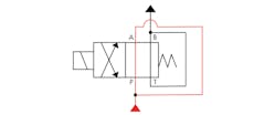
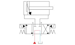
To make a high-flow 2-way valve from a 4-way valve, use the circuit shown in Fig. 2. Connect the pump flow to the valve’s normal inlet port and its outlet port, and then connect the other outlet port to the normal tank port and on to the system. In the at-rest condition, there is no flow through the valve.
When the valve shifts, flow is from port P through port B to the system and from port A through port T to the system. A valve rated at 10 gpm is now good for 20 gpm with little or no increase in pressure drop. For this usage, make sure the valve is capable of backpressure at the tank port. This piping arrangement is commonly used in hydraulic circuits, since most manufacturers do not offer a 2-way valve. Also, many 2-way hydraulic valves only stop flow in one direction, so they are useless in a bi-directional flow line.
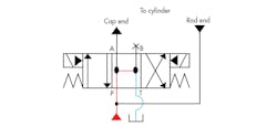
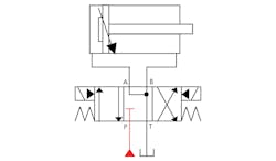
Regeneration circuits can double the extension speed of a single-rod cylinder without using a larger pump. This will reduce costs because a smaller pump, motor, and tank can be used to achieve the desired cycle time. The circuit also will cost less to operate over the life of the machine. For a full-time regeneration circuit, connect the 4-way valve as shown in Fig. 3. When fluid flow is applied to both ports of a single-rod cylinder, it will extend—or at least try to extend. Because areas on opposite sides of the piston are unequal, the cap end of the cylinder always has more force than the rod side.
When a cylinder in a material handling application retracts to pick up another part, it often has to be overextended to make sure it is behind the part. Fig. 4 shows how to pressurize both ends of the cylinder when a 4-way valve centers. Low backpressure from the check valve makes the cylinder creep forward at low power and ensures that the cylinder is in contact with the part before the next cycle starts.
Three-Position Valves
Most hydraulic directional control valves have three positions. When the valve is centered, it can perform several different functions in relation to the actuator and pump. A directional valve that is centered with all ports open unloads the pump and allows the actuator to float, as shown in Fig. 5. This reduces heat buildup and allows opposing forces to move the cylinder without building backpressure.
To block the cylinder while unloading the pump, use the center condition shown in Fig. 6. Because the spools of most hydraulic valves are a metal-to-metal fit that does not block flow completely, the cylinder piston rod may not remain stationary with a tandem-center spool. If there are outside forces on the cylinder, it will creep when the valve centers.
If the cylinder needs to float while pump flow is blocked, use the center condition shown in Fig. 7.
Centered-Spool Conditions
The center condition of a 3-position valve can unload a pump, open actuator ports to the tank for free movement, block actuator ports to stop movement, provide regeneration, or work in combinations of these functions. Figs. 8 to 13 show several commonly used 4-way hydraulic valve center conditions. The first four account for about 90% of all 3-position hydraulic valves in use.
Figure 8 shows a valve in center condition with all ports open. This open center condition unloads the pump and allows the actuator to coast to a stop or float. In the crossover or transition condition, it causes very little shock. This center condition is used with fixed-volume pumps.
A valve in center condition with all ports blocked, as shown in Fig. 9, appears to block the cylinder ports. In actual use, ports A and B are pressurized by oil leakage across the spool lands, which could possibly cause a single-rod cylinder to extend. To stop a cylinder positively, use a valve with the cylinder ports connected to the tank and pilot-operated check valves in the cylinder line or lines.
The valve in float center condition, shown in Fig. 10, allows the actuator to float while blocking pump flow. Pump output is available for other valves and actuators with this center condition. It also works well for pilot-operated check valve locking circuits or with counterbalance valves. This is the normal center condition for the solenoid valve on a solenoid pilot-operated, spring-centered directional valve.
A tandem center valve, as shown in Fig. 11, lets the pump unload while blocking the cylinder ports. This is another common center condition for fixed-volume pumps. The cylinder remains stationary unless an outside force tries to move it. If external forces are acting on the cylinder, it may creep slowly with the valve centered, since a metal-to-metal fit spool valve never blocks flow completely.
The regeneration center position of the valve in Fig. 12 pressurizes both ports of a cylinder and connects them to each other. Connecting oil pressure to both cylinder ports and the ports to each other regenerates the pressure forward when the valve centers. This valve is the pilot operator for hydraulically-centered directional valves or normally-closed slip-in cartridge valves.
To unload the pump while blocking the cylinder from moving, use the valve configuration shown in Fig. 13. Remember that the metal-to-metal fit of the spool will not lock the cylinder completely when there are external forces acting on it.
Figs. 14 and 15 show what is commonly referred to as the crossover or transition condition of a spool. In some actuator applications, it is important to know what the valve port flow condition is as it shifts. As shown in these figures, dash-lined boxes show the crossover condition. Discussions about crossover conditions cover normally open or normally closed types, but in reality, the crossover condition may be a combination of these and may be different on either side of center. An open crossover condition stops shock as the spool shifts, while a closed crossover condition reduces actuator override travel. If the crossover condition is important to the circuit or machine function, it should be shown on the schematic drawing.
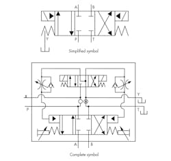
Figure 16 shows both the simplified and complete symbols for a solenoid pilot-operated valve in an all-ports-blocked center condition. On most schematics, the simplified symbol is sufficient. The solenoid slash and energy triangle in the operator box show the valve has a solenoid-operated valve piloting a pilot-operated valve.
The boxes show the function of the main or working spool that controls the actuator. On valves with other hardware added (such as the pilot chokes and stroke limiters shown here), it is better to show the complete symbol. Both symbols in Fig. 16 represent the same valve. The complete symbol gives more information about the valve function and helps with troubleshooting and valve replacement.


