This series of symbol and schematic based issues has been challenging to create. Regardless, this issue is the last of the symbology related issues for a while. I asked for (and received) some good ideas for upcoming issues, but that’s for the future, so let us get down to business with the second part in as many installments of the directional control valve symbol and schematic issue.
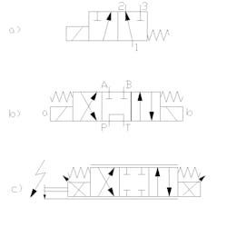
I’ve created two main drawings for this issue (using the free CAD sWhen the solenoid is activated, the coil shifts the valve to the left envelope and fluid is directed now from port 1 to port 3. As you would have guessed, we call this a 3/2 valve, having three ways and two positions. If we need to further describe the valve in example a, it can be said that it’s also solenoid operated and spring offset. The electrically actuated solenoid symbol is the rectangle out the bottom left side with the diagonal slash through it.
For example b, we ramp up the complexity a little (these are going to get more difficult, so stick with me). This is our first example of the ultra-common four-way, three-position directional control valve (4/3 valve, if you will). I have included the electrical solenoid coil designations in this symbol, “a” being the left coil and “b” being the right coil, as would be typically used in Bosch Rexroth nomenclature for example.
The biggest difference between a two-position valve and a three-position valve is the three-position valve has a center — or neutral — position. The center condition of a 4/3 valve can be just as varied as the rest of the valve configuration. The center condition in this valve is often called “tandem center,” because flow in neutral is from the pressure port to the tank port; this allows you to add a second valve, in tandem, downstream of the first.
If you described the valve as “A and B blocked with P to T in neutral,” you’d sound like you knew what you were talking about, even amongst a group hydraulic specialists. The work ports in a 4/3 valve are almost exclusively labeled A for the left work port and B for the right work port. By firing the b coil, the valve shifts to the right side envelope. Fluid previously rivering from P to T is now being forced from P to A. Since fluid is most likely coming back from an actuator, fluid would also be travelling from port B to port T and then back to tank.
Those of you shooting first and taking names later may have missed out on an interesting detail; those of you taking notes first with a shooting pain from carpal tunnel later may have noticed firing the b coil actually results in fluid exiting port A. All I have to say about that is, “interesting.” Moving on…
The 4/3 valve in this case is spring-centered, rather than -offset. When power is removed from the b coil, the springs push the valve back to the centre. Firing thea coil obviously has the opposite effect in that it results in fluid being sent from P to B.
The next valve in example c is quite similar but with a little added geometry. The first difference is the center condition is now completely closed. Shockingly, we called this a closed center valve; ”I know, right?” Fluid is blocked at all ports, both in and out of the valve.
The addition of the two parallel lines above and below the symbol denotes the valve is proportional. I suppose the lines are trying to convey the position of the valve can be anywhere along that line – from partially open to fully open. The variable positioning ability comes from variable electrical current applied to the coils. As you already know, this is represented by the diagonal arrows through the coil symbols.
For more information on proportional valve operation see my August 2011 issue. Not covered in that issue is the feedback concept. The small arrow coming down from the a coil to the bottom “proportional line” tells us the valve is measuring the distance the spool travels along that line. The lightning bolt arrow tells us that measuring occurs electronically.
This is a proportional valve with internal position feedback. The valve will contain what is called a Linear Variable Differential Transformer, or LVDT. That’s a fancy term to say the position of the spool is accurately measured to determine if its actual position matches the desired position relayed to the valve by the controller. Another term for this type of feedback is “closed loop control.” This is extremely accurate, with some of these high response proportional valves being able to match the performance of a servo valve.


