Download this article as a .PDF
The control of fluid power provided by numerous types of pneumatic valves brings industrial machine motion to life. Several of these valve types are standalone and individually mounted, requiring a connection to each valve. Manifold-mounted, compact modular valves provide a better option for systems with three or more valves because they simplify configuration, installation, operation, and maintenance.
This article will briefly discuss available valve configurations, with the focus on the key design features of modular valves. It will also discuss the use of industrial Ethernet protocols such as EtherNet/IP to operate these valve banks. Application examples are included to highlight the advantages of the distributed control enabled by modular valves.
Overview of Valve Options
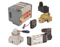
There are many pneumatic valves to choose from when designing an automated machine (Fig. 1). General-purpose valves are often used to control pneumatic actuators and cylinders. Air-piloted valves work well in hazardous areas because they don’t require electrical power. Manual valves are available for hand operation, and pipeline valves control flow of a wide range of process fluids.
A general-purpose valve, often called a directional control valve, is the workhorse of pneumatic fluid power. It is available in a wide variety of body styles and configurations. The simplest valves are 2-way, similar to a normally open (NO) or normally closed (NC) relay contact, and 3-way, similar to a single-pole double-throw relay contact. Another common control valve is the 4-way. This valve switches the air supply and exhaust between two outlet ports, and is most commonly used to actuate cylinders and actuators.
While most valve types can be manually operated, solenoid-operated, or air-piloted, in many machine automation projects valves are electrically (solenoid) controlled and used to create mechanical motion by pressurizing pneumatic cylinders and actuators.
With solenoid-operated valves, providing power to the electrical coil directly operates a spool, plunger or poppet which opens or closes a valve. A common solenoid voltage used in automated machines is 24 Vdc but 12 Vdc, 24 Vac, 120 Vac and 240 Vac are also available.
Air-piloted valves operate like solenoid-operated valves, but use air to operate the spool. This piloted air can be from a remote valve or internally piloted. A small, integrated electrical solenoid is used in internally piloted valves to activate a larger valve spool.
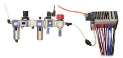
A single general-purpose valve can be surface-mounted to a plate or machine leg, or can be directly mounted to a manifold. The valves can also be stacked together using a series of O-rings and various length screws. Other stacking methods eliminate the screws to create modular valve manifolds. If several valves are needed in an automated machine, these manifold-mounted or modular valves are often the best option (Fig. 2).
Compact Modular Valves
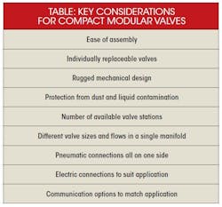
Compact modular valves are often the best choice for automated machines with multiple pneumatic motions, and there are many features to consider when specifying them (see table). These machines often require the performance, flexibility, and modularity provided by multiple valves due to the machine cycle rate and number of actuators.
Distributing multiple valve manifolds around a machine can shorten air lines to cylinders and actuators, resulting in simpler integration and faster actuator response. An industrial environment also requires simplified plumbing, sturdy mechanics, a high degree of protection, and integral control signal routing.
Ease of assembly is often a driving factor on any machine or piece of equipment. The design of some compact modular valves, whether stacked together or mounted to a multi-position manifold, include built-in captive screws in a valve for easy assembly. Designs where the manifold can be split in the middle, without disassembling multiple valves from one end, speeds adding valves or replacing worn valves during maintenance.
Rugged mechanical design ensures a long operating life in harsh service. A valve enclosed in a reinforced protective shell can act as a shock-absorber and prevent the infiltration of dust and dirt. A smooth, rounded valve design should also be considered for applications requiring frequent washing.
For valves to survive in an industrial setting, they must have the appropriate environmental rating. Some valves don’t include protection from dust or liquids, while others have a dust-proof enclosure but are vulnerable to liquids. If protection from dust and liquids is a requirement, valves with an IP65 rating should be specified for protection from dust ingress and low-pressure water jets. A rating of IP67 or higher should be considered if immersion in water is possible.
Modular valve banks offer a variety of configurations from 1 to 32 solenoids. This range fills a variety of applications but 8 to 16 solenoids is a more common range. It is best to have valve banks that support mixed valve sizes supporting different tubing and flows as some actuators will require more air flow than others. Common port and tubing sizes on automated machines range from 5/32 to 3/8 in., and 4 to 10 mm.
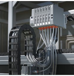
To simplify plumbing installation, all the pneumatic connections should be on one side of the modular valve bank and include built-in push-to-connect fittings. While main air supply and exhaust is usually fed to one or both ends of the manifold, connecting the control air to the cylinders from a single side of the manifold simplifies installation (Fig. 3).
Discrete Cables vs. Industrial Ethernet
It’s often necessary to use different inlet/exhaust end plates and intermediate modules to provide the flexibility required to operate valve banks at vacuum or dual pressures, and to improve air and exhaust flow. These end plates also provide communication options, either discrete or digital.
As a modular valve assembly is stacked together or mounted to a manifold, the electrical signals need to be robustly relayed from one valve to the next or fed through the manifold. Many designs provide built-in connectors among valves to bus up to 25 or more wires through the manifold. Some even use integral, feed-through contacts for simple and robust electrical connections. Other manifolds may require careful connection within the manifold during assembly or when adding stations, which is not optimal.
The discrete option typically uses one of three electrical connection methods including hard-wired, modular-wired, or digital communications. Individual valves typically have flying leads, a built-in connector with a pluggable flying lead cable, or a DIN style connector.
With manifold-mounted valves, the modular wiring typically includes a multi-pin D-sub connector or circular-DIN connections. Modular valve wiring may also include industrial Ethernet and fieldbus digital connections. While these digital connections often require a separate power cable and ground be run to the manifold, the use of Ethernet digital communication protocols is becoming popular for a variety of reasons.
In many modular valve manifolds, simply specifying a different end plate or electrical connection box changes the fieldbus or Ethernet protocol. Some popular digital protocols include AS-i, CANopen, DeviceNet, Interbus-S, and Profibus-DP. IO-Link technology is also available with modular valves, and it includes both communication and power, provided by the IO-Link master, in a single cable.
Industrial Ethernet and related protocols are also popular choices when connecting to modular valve manifolds. Leading protocols include EtherNet/IP, Modbus/TCP, PROFINET, CC-Link IE, EtherCAT, POWERLINK, and SERCOS III. These protocols can be used to control 32 or more valves, and expand to additional manifolds where needed.
Advantages of Digital Communications
Digital communications minimize the number of wires and cables running from the control system to the manifold. It also allows the manifold to report status indication back to the control system. Flexibility is increased because valves or manifolds can be added without running new wires from the control system. Multiple I/O points and possibly entire I/O modules at the controller are replaced by one digital communications port, saving space and money.
With digital communications such as EtherNet/IP, it is necessary to initially configure each modular valve manifold and create the related configuration in the controller. The IP Address, Subnet Mask, and Default Gateway must be configured in the valve manifold to work with the controller’s EtherNet/IP Scanner or Client module.
However, once this is done, it’s simple to apply the same configuration over and over for multiple machines. As another benefit, if the modular valve manifold is added to a production line or machine that already has a network, minimal work is required to plug it into the existing network and run a power cable to the manifold.
Using digital communication instead of discrete also opens the door to more diagnostic information from the manifold to the controller. Cycle counts, short-circuit status, current sensing, communication status, and module faults are just some of the diagnostic information that may be available.
Summary
In machines and systems with multiple pneumatic valves, consider compact modular valve manifolds. With the wide variety of valves available and multiple communication options—including industrial Ethernet—the resulting pneumatic control system will be simple to install, maintain and modify.
Chip McDaniel is in technical marketing at AutomationDirect, Cumming, Ga. For more information, call (800) 633-0405.
