Download this article in PDF format.
Control using electrohydraulic proportional or servo valves is usually achieved by using a power unit that maintains a constant inlet pressure to the control valve. Such a design strategy offers several advantages and raises several issues:
- With a high-pressure supply, hydraulic power is available immediately when a signal is given to open the valve. That is, there is no need to wait for pump pressure to build before flow occurs and the load moves.
- Conventional servo and proportional valves can be used because nearly all have a closed-center center-spool position.
- Because the valves are closed center, a pressure-regulating supply must be used. Pressure-compensated pumps are a frequent choice for regulating pressure.
The greatest accuracy is achieved by regulating the valve supply pressure to the lowest practical tolerance. That is, supply pressure is kept constant, regardless of the variation in flow demand by the load.
A pressure-compensated pump may be able to supply hydraulic power at a relatively constant pressure in the face of flow demand changes that can suddenly increase from zero to maximum, and vice versa. Then again, it may not. Depending on the circumstances, an accumulator may be used to supplement pump flow during brief periods of peak flow demands. But often, the pressure-compensated pump by itself will suffice.
This begs the question: Do any simple rules of thumb exist to help circuit designers determine the need for an accumulator? The short answer is yes, and my immediate aim, here, is to explain how it works. I'll introduce a sample system to explain the process.
A Sample Scenario
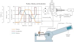
The sample system is typical of a position feedback servo system that follows a command profile (Fig. 1). The graph on the left shows the acceleration, velocity, and distance motion command profiles. A simplified circuit is on the right, and an illustration of the physical installation is shown at the bottom. The cylinder has a bore of 2 in. and a rod diameter of 1 3/8 in. to accommodate gun-drilling for a magnetostrictive position transducer. A piston pump with a conventional pressure-compensation mechanism drives the system.
1. The laboratory test setup closely emulates dynamic behavior of a typical industrial electrohydraulic system. Note that instead of using a pump symbol, the illustration shows a constant-pressure source such as a pressure-compensated, variable-displacement pump with output augmented by an accumulator.
As with all electrohydraulic position servo mechanisms, the cylinder is fitted with a position transducer that feeds a signal back to a summing junction in the servo amplifier. The command signal into the summing junction is the position profile from the graph of Figure 1. This signal, of course, would be supplied by a control computer or motion-control card from a programmable logic controller (PLC).
As the command profile voltage rises, the error between it and the feedback is amplified in the servo amplifier. The amplifier then opens the valve, which directs flow to the cylinder, causing its motion to try to keep up with the command. The result is a regular, cyclic cylinder motion that continues as long as the command profile repeats.
This system was chosen because it is a research tool that was used in my IDAS Engineering research lab. The performance graphs provided in this article are real data, not theoretical. They could be data collected from any industrial machine that undergoes regular, reasonably uniform, cyclic motion. The laboratory simply offers the opportunity to monitor and record all of the key performance variables.
Mapping Out Tests
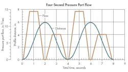
Two tests will be conducted on the sample system. The first will use only a pressure-compensated pump with no accumulator. It will be controlled by a command profile that requires four seconds to complete one cycle. Two complete command motion cycles are shown in the graphs in Figure 2. This display strategy improves the graphical data presentation regarding the pressure changes.
2. Results from the test show relationship between flow and displacement.
The command distance profile and the resulting pressure-port flow to the valve are shown in Figure 2. Note that the command profile in Figure 2 differs slightly from that of Figure 1. This occurs because the command used in this series of tests has slightly shorter dwell times at the ends of both extension and retraction. This difference has no effect on the observations or conclusions we are about reach; it is merely noted for the record.
The second test will also be conducted without a supplementary accumulator. However, the motion command profile will be accelerated so that its cycle will complete in only 1 second. It has the same general shape as shown in Figure 2, but everything will be commanded to happen four times faster.
Two different flow peaks exist during each cylinder cycle in Figure 2. The higher one corresponds to the cylinder undergoing extension. The lower peak corresponds to the cylinder during retraction. The difference, of course, is caused by the area differences between the rod- and cap-end sides of the cylinder. The volume of fluid consumed by the moving cylinder is simply the area under the flow graph.
Now let's review the motion and flow profiles in Figure 2. The motion has a short dwell, at the end of which a uniform acceleration occurs, reaching a speed that causes an extension flow of about 14 in.3/sec. The acceleration time is about 0.6 sec. Next, a constant-speed period lasts about 0.6 sec at the 14-in.3/sec flow mark; then deceleration to zero occurs in another 0.6 sec. Flow returns to zero again at 1.9 sec.
A dwell of about 0.2 sec occurs at extension, followed by retraction, which starts along a motion profile that is identical in time increments to that of extension. However, the cylinder area difference (a ratio of 1.896:1) results in a peak flow of about 7.5 in.3/sec. Meanwhile, the cylinder motion, which is almost sinusoidal, results in a maximum extension to about 5.7 in., and then retraction to about 0.3 in.
The flow profile must be supplied by the pressure-compensated pump. If pressure at the pump outlet is to remain constant in the face of the flow variations, then pump displacement must undergo substantial changes. No compensator can perfectly adjust the pump displacement, so some pressure variation must always accompany a flow variation. The aim is to keep the pressure fluctuations within tolerable limits. An intolerable limit occurs, of course, when the pressure variations are so extreme that the cylinder does not follow the command profile within acceptable limits.
The Second Test
A second test also will be conducted without a supplementary accumulator. However, the motion command profile will be accelerated so that its cycle will be completed in only one second. It has the same general shape of that in Figure 2 but everything will be commanded to happen four times faster.
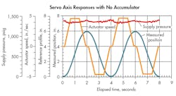
Figure 3 reveals the results of using the first command profile—i.e., the one that takes four seconds to complete. Four different traces are shown. The command profile and the measured position (piston motion) lie almost atop each other. This occurs because a very good servo loop is established. Very little error exists between the command and actual positions because servo-amplifier gain is very high.
3. With four seconds to complete a motion cycle, very little error exists between the command and actual positions.
Figure 3 also shows the actuator speed. This value is calculated by differentiating the measured position with respect to time. It clearly shows the dwell times at extension and retraction, the acceleration and deceleration periods, and the nearly flat-topped "constant speed" portions.
Rather than being induced by actual speed variations, the squiggles at upper and lower extremes of the speed trace are caused more by the inevitable consequence of measurement noise that is enhanced by the differentiation of measured data.
The supply (P-port) pressure is also shown as a slightly cusped curve with some small squiggles caused by the dynamic response of the pump compensator. It is traced out near the top of the graph axes.
The pump's compensator initially was adjusted to produce a deadhead pressure of about 1,400 psi. As expected, the average dynamic value of supply pressure is slightly less than 1,400 psi. But more importantly, the pressure variation is only about 100 psi between the highest and lowest measured values. This performance probably is completely acceptable for all but the very critical applications, and it was accomplished without an accumulator.
Speeding It Up
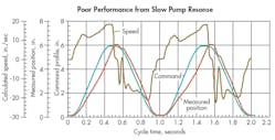
Figures 4 and 5 show the results of reducing the cycle time from one cycle every four seconds to one complete cycle each second. This is a rather severe increase, but not unreasonable in today's industrial environment. Again, no accumulator is used in this test.
4. Increasing the work-cycle frequency creates a large error between the command and the measured position profiles, which is unacceptable for most applications.
Note in Figure 4 the poor compliance between the command and measured position profiles. A large error exists between them, which signifies very poor performance of the servo loop, and is probably unacceptable in any application. The cylinder velocity no longer is a clean trapezoid, as in Figure 3. The velocity was corrupted by the pump's inability to compensate for the rapid flow demand variations.
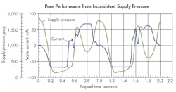
The reason for the poor following performance in the servo loop is revealed in Figure 5, namely, the supply pressure. It varies from about 1,900 psi to a low of about 200 psi. At the same time, the servo-valve current swings from ‒70 mA to +70 mA—the saturation limits—as the servo loop tries to keep the cylinder in sync with the command profile.
Two major issues are at play here: First, the flow demand profile is requesting flow increases and decreases that the pump's pressure-compensating mechanism cannot keep up with. This contributes significantly to the wild fluctuations in pump supply pressure. Second, the reduction in the command profile time was "constructed" with the same total cylinder travel distance. This quadruples the peak flow demand in this faster cycle.
Although not shown, the ideal peak flow is about 56 in.3/sec, as compared to 14 in.3/sec in the first test. Clearly, the pump is being asked to increase and decrease its displacement by an amount four times as great, thereby "penalizing" the pump—i.e., imposing a much more severe test condition in this second case. But this is realistic for an industrial application that must provide variable production rates. The cylinder must travel the same amount, and the application requires that it do so four times faster.
5. Demanding peak flow that a pump is unable to deliver causes supply pressure reductions that decimate servo-loop performance.
Now, with that revelation having been made, it also follows that the average flow must be four times greater in the second case—not just the peak flow. Clearly, then, the higher cycle rate would benefit from an augmenting accumulator connected directly to the inlet port of the control valve.
Summing It Up
The pump used in these tests is advertised to have about a 145-msec response time. In other words, it can go from zero to full stroke in that amount of time. So a simple-to-use rule of thumb is needed to help designers know when an accumulator is absolutely necessary, and when they can get by without one. We need only compare the published pump response time to the time required to change the flow in the application.
Recall from the first test (with the four-second profile) that 0.6 sec were expended in changing the demand flow from zero to maximum. This is four times longer than the pump's response time. In contrast, the higher cycle-rate profile reduced the flow increase time to only 150 msec, which caused a clear failure in performance.
Here is the rule of thumb to decide if you can get by without an augmenting accumulator in conjunction with a pressure-compensated pump: No accumulator is required if the flow change time in going from zero to maximum flow, or from maximum to zero flow, is three or more times longer than the full stroke response time of the pump.
This application, with the shorter cycle time, could benefit from an accumulator. With an accumulator installed, the opening of the valve at flow-increase time would use flow from the accumulator to fulfill the sudden flow demand. This applies not only to discharging the accumulator, but for recharging as well. The pump leisurely changes displacement to meet the average flow demands, and the accumulator reacts to rapid changes in demand.

