Certain industries have testing applications that require the exertion of large amounts of force. In those cases hydraulics is the power of choice, with an electrohydraulic motion controller performing closed-loop control to ensure that the force is applied with accuracy and precision.
An example of such a high-force testing environment is the system developed by Dril-Quip Inc., Houston, to verify the functionality and structural integrity of subsea oil-well connectors. Obviously, the safety and ecology of offshore oil operations depends on the utmost care being applied to ensure that the components of oil-production systems function as designed.
Among the components that Dril-Quip manufactures are connectors used for joining segments of well casing. In offshore well installations, an assembled stack of these casings and connectors can extend thousands of feet into the seabed, establishing the foundation of the subsea well. Ocean wave and current action and the motion of the drilling rig pushing on the riser pipe, plus the weight of the oil well blowout preventer (BOP), exert tremendous bending loads on the wellhead system and connectors that hold casing sections together.
“To simulate the worst of real-world conditions in testing our connectors, we needed a hydraulic test platform that can apply a huge amount of bending moment on the connections,” said Mike Lynch, P.E., senior scientist engineer at Dril-Quip. “And the platform needed to incorporate multiple cylinders, operating simultaneously, but with different control inputs, in order to produce both compression or tension and bending force on the test specimen in various combinations.”
“And we needed to apply the force precisely, up to 95% of the amount of force required to make the connector yield. In other words, we needed to bend the connector, but not beyond the point where it would not return to its original shape,” continued David Trevas, Ph.D., senior scientist engineer at Dril-Quip. At only 40 to 70 ft away from the first casing connection, the wellhead system itself would also need to be tested in the same manner to validate safety factors and overall system robustness.
New Test Apparatus Required
The test procedures for various oil well components are defined by the American Petroleum Institute (API), the dominant industry organization in the U.S. What’s innovative about the Dril-Quip setup is its ability to test large surface and conductor pipe connections and wellhead systems.
“Whereas most manufacturers test each component individually, we wanted to be able to test our components in a more realistic system configuration,” said Lynch. “We wanted to put an entire 20-ft-long wellhead system into the apparatus for the combined bending-load-pressure test.”
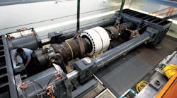
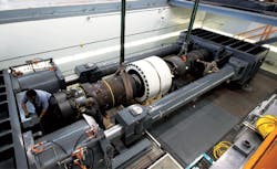
Because no such test frame existed for the size and magnitude of the loads required for this type of testing, one had to be constructed. In the new frame that Dril-Quip designed, a pair of hydraulic cylinders plumbed in parallel is mounted horizontally to a fixed beam at one end and connected to an articulating beam through two connecting rods at the other end of the fixture (Fig. 1). The test specimen is also affixed between the two beams.
To apply different bending and load combinations, the system operates the cylinders to exert a different amount of force on each end of the articulating beam. To supply adequate force, the cylinders have a bore of roughly 4 ft and stroke of 6 ft. Each double-acting cylinder can generate 6.5 million lb of force. The frame can also apply a bending moment of more than 20 million lb-ft. It has a unique ability to exert large tensile or compressive forces simultaneously with a large bending moment.
Controlling the Motion
To control the hydraulics in the new test frame, the Dril-Quip team searched the Internet for electrohydraulic control systems that not only could meet the precision and accuracy requirements of the tests, but also could be easy to program and tune. The search led to Delta Computer Systems Inc.
“We didn’t want to have to write the closed-loop control program from scratch,” said Lynch. “Delta’s RMC 150 controller has built-in support for force and position control and synchronizing the motion of multiple axes, saving us lots of development time and effort.”
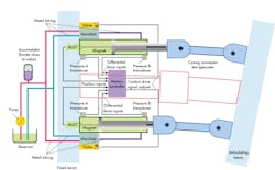
To control the applied force, the Delta RMC150 measures the pressure on each side of the piston in each cylinder with pressure transducers (Fig. 2). Computing the differential pressure yields the force applied by each cylinder individually. Simultaneously, the controller uses cylinder position information from magnetostrictive linear displacement transducers (MLDTs) mounted in the cylinders to monitor deflection of the wellhead system under test. The position measurements provide a way to check the amount of bend and verify that the yield strength of the specimen has not been reached.
With both types of transducers installed in the system, the RMC150 can react to pressure and position information at the same time in controlling up to eight motion axes simultaneously. No special interface hardware is required to connect pressure and position sensors to the controller, and up to 16 different transducers can be connected to the controller at the same time.
Strain gauges are also mounted on the test sample and used to verify the test forces being applied. Data from these gauges are sent to a PC running LabWindows data-acquisition software from National Instruments, Austin. When the system is turned on, it moves to apply the force that is instructed by a test profile set up on the PC and communicated to the motion controller via an Ethernet link.
The assembled test specimens, which can vary from 20 to 42 in. or more in diameter, are subjected to various load conditions and monitored for leaks. To be qualified for service, these components must withstand combinations of loads and moments while enduring internal or external fluid pressure without leaking.
Programming the Motion
Programming the motion controller consists of writing a sequence of motion steps for each axis into the RMC150’s memory and setting up the synchronization relationship allowing the two axes to work together. As the system was operated, the Dril-Quip team tuned the motion by referring to motion plots produced by the Plot Manager, one of the software programs in Delta’s RMCTools programming package.
Figure 3 shows the forces generated in the hydraulic cylinders, their displacement, and the bending moment exerted on the specimen. This test combined moments exceeding 10 million lb-ft with a 1 million-lb tensile load, explaining why the force curves are not mirrored about the horizontal axis of the graph.
Pressurized internally with fluid, the specimen itself contained an internal hydraulic load cell. As they were activated during the test, the hydraulic forces within the load cylinders were adjusted to maintain the desired bending moment. The motion controller kept the target of combined moment and load constant, even as the contributing forces varied.
Realistic Results
The testing of manufactured components under real-world conditions is an important adjunct to mathematical methods of structural simulation such as finite element analysis. As Dril-Quip demonstrates, testing at the highest-possible levels of system integration can enhance the value of physical testing.
Although the theoretical models are used for verification of the structural components in their ideal forms, real-world validation tests on physical assemblies validate component interactions that result from complex loading conditions. With a flexible test bed and a programmable motion controller operating it, a wider set of conditions can be tested, and confidence in the functionality, reliability, and safety of the manufactured products can be improved.
Bill Savela is technical marketing & sales director at Delta Computer Systems Inc., Battle Ground, Wash. For more information, call (360) 254-8688, or visit www.deltamotion.com. For a more in-depth discussion of this test fixture and its capabilities, go to bit.ly/HP147Wellhead.


