Download this article in PDF format.
Amplification is, arguably, the most important contribution of electronics. So important, in fact, that it has had a profound effect on entertainment, radio and TV, and automatic control systems in both home and industry. The implications are far-reaching indeed. Nonetheless, it is as much concept as it is reality.
To the uninitiated, it may seem like the efficiency of amplifiers is more than 100%, where we get something for nothing. This misinterpretation is understandable, because with amplification, we can take the millivolt level signal from, say, a pressure transducer, amplify it electronically, and have enough power in the output to energize the solenoid on a proportional valve. Is this not getting something for nothing? Well, yes and no.
For one thing, the efficiency is not over 100%. Perpetual motion remains beyond the reach of we mere mortals. But it is true that amplification is both real and a matter of interpretation. It’s important enough as a topic to emphasize it a bit more here.
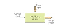
1. Amplifying devices have two inputs, one for power and one for control.
Amplification was discussed previously and contrasted with the other type of input/output device, the transformer. The reality of amplifiers was that all amplifying devices have one output and two inputs. One input—the one that is many times forgotten or at least taken for granted—provides the necessary power so that the amplifier can function. A second input is the controlling input.
The amplifier shown in Fig. 1 is in simple block diagram form with the required power input power, control input port, and amplified output port. Transforming input/output devices (Fig. 2) do not have the control input, and therefore cannot be classed as amplifiers. All of the output power must come in through the one and only input port. Typical transforming devices, such as electrical transformers, fixed gear boxes, fixed displacement pumps and motors, permanent magnet dc motors and generators, induction motors, etc., are not amplifiers.
2. Transforming devices, such as gear boxes and electrical transformers, have no control input port, rather only input and output ports.
Investigating Gain
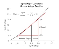
The term gain, when applied to amplifiers, is the ratio of the change in output divided by the change in control input that caused the change in output. It is necessary that some specific and repeatable output results from a specific input.
For example, the control input in Fig. 3 might be 1.5 V, and the output could be 15 V. If the input voltage is changed and then returned to 1.5 V, we expect that the output will return to the 15-V point. It could lead us to conclude that the voltage gain is 10 V/V. That may or may not be the correct value for the gain because we have to record the changes in output with changes in input. Or, we might have a different kind of amplifier in which a control input of 1 bar causes an output of 10 bar. The pressure gain could be 10 bar/bar.
3. The change in output for this generic voltage amplifier is about 10 times greater than the causative control input change, producing a voltage gain of 10.
This idea of gain is not interpreted as having an efficiency of 1,000%! Efficiency is the ratio of useful power out to total power in. In the gain calculation, we take into account only the effects of control input relative to the output. The power that comes from the power supply (more on power supplies shortly) has been conveniently ignored. The amplifier’s designer is concerned about the efficiency, but the amplifier user is mainly interested in having the device provide the correct amount of voltage gain.
Understanding Transistors
Transistors perform amplification as their basic function. Its invention, subsequent method of manufacture, and rapid advances have transformed and revolutionized technology more than any other innovation throughout all of history.
Renowned U.S. research engineer William Beaty laments the dismal explanations of how transistors work at the atomic level. He especially laments the use of the black-box approach. However, it’s not necessary to understand the physics of the semiconductor junction to know how to put a transistor work. Nonetheless, the black-box approach is effective in applying transistors and understanding what they do in terms of their function in circuits.
The transistor is a current-amplifying device. That is, a small current into the control input port will control a much larger current at the output port. It is, in all respects, an electronic valve that can be turned on with either input control current or voltage.
MORE ANALOGIES: Brushes and Commutators
A reader recently remarked to me about how similar hydraulic and electric machines are to one another. Indeed, that is the case, but more dissimilarities exist than similarities. The most important one is that there are both dc electrical and dc hydraulic motors, and there are ac electric motors—but no practical ac hydraulic motors. The similarities end with the comparison of the brushed and commuted dc motor to the port-plate hydraulic motor.
What are the functions of the brushes and commutator in electric motors and generators, compared to the port plate in piston and vane equipment? Their purposes are the same: They convert the internal alternating flow into unidirectional external flow. When one looks into the innards of the machine, both electrical and hydraulic machines function with alternating flow.
The bottom line is that there is no such thing as a purely dc machine, either hydraulic or electric. Pistons reciprocate and have alternating flow in their bores. Armature windings on dc motors undergo current reversals every time the coil segment passes a stator pole piece. No dc here, only ac. So to say that a motor is a generator, or a pump is a dc-operated device, you are speaking strictly from an external point of view. Gear pumps and motors also have reciprocating internal flows. Though the reciprocating flow is more subtle, it’s nonetheless, real.
All ac electric motors evolve from the two basic principles of induction or synchronous types. Getting the rotor to turn requires the existence of the rotating magnetic field. This is not difficult to do: Construct the stator with three windings that are displaced by120 stator degrees and excited by three sine-wave voltages that are likewise displaced in time by 120 degrees. Alternatively, you could use two windings displaced by 90 stator degrees and excited by sine-wave voltages displaced in time by 90 degrees (actually a sine wave and a cosine wave).
A rotating magnetic field will be produced merely by connecting the sine waves to the stator windings. When a rotor is inserted into the motor’s center cavity, the rotor will turn as it tries to catch up to the rotating magnetic field.
An alternating-flow hydraulic motor, like that discussed above, can be made to work. Its practicality is in doubt, and maybe some day manufacturing and pressure-control methods may merge with critical applications to make such machines commercially viable.
The more important concept is that such a motor requires a rotating pressure field. First, the 12 o’clock piston is pressurized, then relieved, followed by the 9 o’clock piston pressurization and its subsequent relief, and so on, around the stator-mounted pistons. Generating a sine wave and cosine wave of pressure would, indeed, create a rotating pressure field, and it would cause the rotor cam to turn at the synchronous speed.
Synchronous speed is the rotational speed of the pressure field. Herein lies the commercial viability issue—it isn’t so much the cost of the four-piston motor, but the cost of generating the two pressure waves. Technologically, it’s possible with well-controlled servovalves. However, the cost would be significant, and the efficiency would suffer greatly because of the power losses coming from the pressure drops across the valve lands and the flow through them.
Comparisons From a DC Perspective
The hydrostatic transmission and the Ward Leonard drive (covered last month) are similar well beyond first glances. The field currents in the motor and generator are almost perfectly analogous to the displacement controls in the pump and motor. And the series-connected dc motor produces a torque-speed characteristic that can be matched almost perfectly with a hydraulic transmission.
The Ward Leonard drive is ancient by technological evolution standards. Differences abound today in the controls for electric drives, such that the controllers connect directly to the ac power-distribution grid and the output is whatever the specific motor requires, be it dc or ac.
Furthermore, both the Ward Leonard drive and the hydrostatic transmission are regenerative in that they are capable of sending the decelerating energy back onto the electrical grid so that other machines in the vicinity can capture that energy and yield overall reductions in energy costs. They can both be very efficient machines. On engine-driven drives and transmissions, other energy-capturing methods are needed, lest deceleration energy be converted to heat as a braking function.


