This file type includes high-resolution graphics and schematics when applicable.
An internet search for hydraulic stepper motor will generate at least one patent on that subject. The principles explained therein are simple, and when carried to their most general concepts, can help understand ac electric motors and the rotating field used to propel either a magnetized rotor (synchronous motor) or the counter-field from current induced into an induction motor rotor.
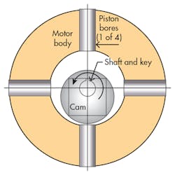
The principle of the hydraulic stepper motor is shown in Fig. 13. It starts with the stationary body of the motor, which houses (in this case) bores that will receive closely fitted pistons. Also shown is the basic rotating assembly, namely a shaft onto which is secured a nonconcentric but perfectly circular cam.
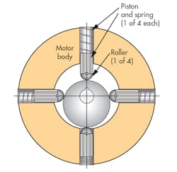
The pistons are then added to the bores (Fig. 14). The pistons are aligned so that their centerlines coincide with the shaft center of rotations. In the position shown in the figure, the keyway will be used as an indexing pointer. This will be called the 12 o’clock position of the output shaft.
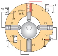
Pressure must be applied to the pistons in a specific sequence in order to get the rotor into its 12 o’clock position and maintain it. Pressure will have to be applied to P1. In Fig. 15, pressurization of the P1 piston is accomplished by shifting valve V1 to its on state shown. Note that the other three valves are all shown in their respective relieving positions, which vents their respective piston cavities to tank.
This machine can operate as either a pump or motor. However, with the valves as configured, it’s going to be explained in its motor mode. It is to be operated specifically as a stepper motor. In fact, if there were an official name for it, it might be “two-phase, radial-piston, fixed-displacement, hydraulic stepper motor.” As the pistons are sequentially pressurized with their respective valves, the rotating group will turn 90 deg. with each individual pressurization cycle. Figure 16 sets up the transition from powering P1 to powering P2.
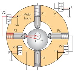
Here are the setup conditions for visualizing the torque generation in the hydraulic stepper motor: First, start under the assumption that the shaft is in the 12 o’clock position, V1 has very quickly shifted from powering P1, and at the same time, V2 just as suddenly shifted to power P2, as shown in the diagram. The valve shifting took place so quickly that the shaft has not yet had a chance to move.
Subsequently, with hydraulic pressure applied to piston P2, and with the pressure relieved in piston P1, piston P2 generates a force proportional to the piston area times the pressure. Because of the low friction between the nose roller of piston P2, the force can be transmitted only in a direction that is perpendicular to the tangent line of contact between the roller and the non-concentric cam’s outer surface. The result is a torque that acts on a torque arm of length BC, which causes the cam and shaft to rotate counterclockwise.
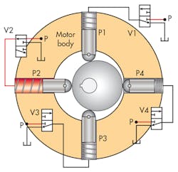
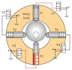
But how far will the shaft rotate? It will rotate only 90 deg., until the keyway is in the 9 o’clock position (this is not shown in the figure). However, it should be easy to visualize that at the 9 o’clock position, the net piston force passes directly through the shaft centerline because the point of roller-to-cam contact is perpendicular to the P2 centerline. No torque will be generated and the rotor will stop at the 9 o’clock position. By shifting one valve at a time in the proper sequence, the shaft can be made to move a ¼ turn at a time (Figs. 17 and 18).
Motor Types Mirror Each Other
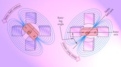
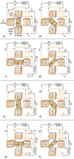
This hydraulic stepper motor is perfectly analogous to the electrical stepper motor, Fig. 19 , which has steps that include simultaneous energizing of adjacent stator coils. The result is the ability to achieve the intermediate shaft positions between the 12, 9, 6, and 3 o’clock positions. The same can be accomplished with the hydraulic stepper motor. In fact, if the P1-to-P3 differential pressure is a cosine function while the P2-to-P4 pressure is a sine function, the motor will rotate at the frequency of the sine and cosine functions.
Stepper-motor usage has a simple premise from the user’s viewpoint: We want to send a series of electronic pulses, and have each pulse result in a specific angular position change of the output shaft. For example, we may want a pulse train consisting of, say, 52 pulses to result in a precise change in the shaft angle of 52 deg. The basic idea behind a user-friendly system is given in Fig. 20. Accurate incremental division requires that the piston pressures be precisely controlled and coordinated.
In this example, the resolution of the stepper-motor system would be 1 deg. per input pulse. Then, by way of lead screw, rack and pinion, or other rotary-to-linear translator, linear position can be achieved without the need for closed-loop feedback control systems. When the controller consists of the simple on-off valve system suggested in Figs. 15 through 18, the resolution of the system is 90-deg./pulse (valve shift operation, one at a time). A more sophisticated electronic control method is required, allowing for what is referred to as microstepping.
Microstepping in the Hydraulic Stepper Motor
Microstepping is a control method that takes advantage of the ability to apply pressure simultaneously to more than one piston at a time, allowing for a great number of intermediate steps. The previous figures show a two-phase stepper motor, which has four pistons, each of which is displaced by 90 deg. from its neighbors.
As explained previously, separate excitation of each piston individually results in angular movement in multiples of 90 deg. Therefore, the native step size (its resolution) is 90 deg. per valve shift event. However, it was also explained that intermediate positions can be obtained if two pistons are pressurized simultaneously. If the two pressures are equal, then intermediate 19 positions of 10:30, 7:30, 4:30 and 1:30 are possible. Are other intermediate positions possible with unequal pressures? Definitely!
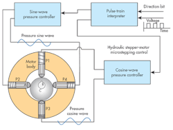
The simple geometry of the hydraulic stepper motor, consisting mainly of the non-concentric but circular rotor cam and the 90-deg. piston displacement, lend themselves to sine- and cosine-wave excitations in order to achieve microstepping as well as optional continuous rotational motion, as with a conventional motor. The basic idea is shown in Fig. 21.
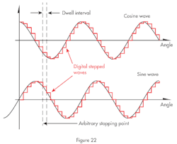
By controlling the P1-to-P3 pressure in the form of a cosine wave and the P2-to-P4 pressure as a sine wave, the potential exists to achieve any desired final stopping point. The two wave shapes and their digital equivalents are shown in Fig. 22.
Pulse-Train Interpreter
To achieve microstepping, the simplified controller in Fig. 20 must be expanded to take a little closer look at what’s inside the “stepper-motor controller” box. Some of that detail is shown in Fig. 21.
Here, it’s seen that there is a “pulse train interpreter” electronic function. This is actually a digital controller with math capability (control computer)—it can accept and process the pulse train as well as generate the sine and cosine signals needed to control the two differential output pressures that go to the P1-to-P3 and P2-to-P4 piston pairs, respectively. This pulse-train interpreter function also keeps track of the net number of pulses that are received via the input pulse train; this lets the controller “know” where the shaft is positioned.
In Fig. 22, cosine and sine waves are shown in their “ideal forms” as black wave shapes. In digital systems, everything is done in steps, or in finite increments (these are shown in red). It results in wave shapes that are staircased with dwell levels connected together by very rapid (vertical) changes. This is a reality of the digital world, and is actually a benefit in the microstep control system and motor.
The pulse-train interpreter also receives a second input, labeled direction bit in Fig. 21. The direction bit is a single line input that is either a logical 1 or a logical 0. It tells the interpreter the direction of shaft rotation by controlling the sequence in which piston pressures change.
This need is best seen in Fig. 16. As shown, the shaft rotation will be counter-clockwise. For continued counter-clockwise rotation, the valve sequence is V2, V3, V4, V1, V2, etc. However, if the sequence is reversed to V4, V3, V2, V1, V4, etc., rotation will be clockwise. Such directional protocol is necessary whether the pressure is the simple case of Fig. 16 or the more sophisticated microstepping control of Figs. 20 and 21.
Sine and Cosine Pressure Controllers
The sine and cosine pressure controllers in Fig. 21 receive the digitized sine and cosine signals from the pulse-train interpreter (red wave shapes in Fig. 22) and generate proportional differential pressures. They will likely consist of servovalves driven by a PID servoamplifier, operating in a closed-loop configuration with the pressure measured by differential pressure transducers.
This method assures that the two differential pressures follow their respective staircase commands, and do so with essentially zero steady-state error. Accurate control of the two pressures is absolutely essential to accurate microstepping.
The dwell interval in Fig. 22 is a somewhat arbitrary interval in both angle and time. In terms of time, it is basically the time between successive pulses in the pulse train. Earlier, a step resolution of 1 deg./pulse was discussed. In Figure 22, the resolution is much greater—in fact, it is 22½ deg. The drawing was made with 16 steps because 360 steps would be invisible on such a small figure. So, 360 deg/16 = 22½ deg.
As the train of input pulses continues, the two pressures staircase along the red trajectories of Fig. 22. At the same time, the shaft is stepping along in synchronism with the pressures, provided that the steps do not arrive too fast. If some maximum rate of sending the pulses is exceeded, the shaft will drop behind the pulse train, causing an error in the output position.
Barring that eventuality, when the pulse train stops, the shaft stops, and is in its correct position. When the pulses stop, the pressures stop changing, and the shaft is held in its latest position. When the pulses stop arriving, the pressures do not go to zero. Instead, they are held at those values commensurate with the staircase wave shapes of Fig. 22 by the restorative torque of the pressurized pistons.
Stepper-Motor Tuning
It is possible to input a pulse train with pulses that arrive so fast, it causes some of the steps to be dropped. Therefore, it is necessary to “tune the motor” to prevent these drops. Actually, it’s the controller that needs to be tuned, but the jargon refers to the motor, which persists to this day.
Tuning consists of setting the microstepping resolution and not sending the pulses too fast (avoiding too high a frequency). Resolution is set by the requirements of the application. It is affected by any gearing, lead screws, or belts that may be connected to the ultimate load, and then determining the minimum change required in output position.
The next step is to begin increasing the pulse-train frequency until a loss of steps is observed, and then backing down by an amount that results in a smooth and continuous shaft and load motion without jerkiness. This must be done with the exact controller electronics: the exact stepper motor and the motor connected through its gear or belt linkages to the exact load that is to be moved and controlled.
The maximum pulse-train frequency limits the slew speed of the system. It is significantly affected by the inertia of the motor’s cam and shaft, but also by the amount of load inertia. This is why the whole system has to be tuned—if the load inertia changes, it could result in utter failure to attain the performance goals of the system.
Summary of Hydraulic and Electric Stepper Motors
The hydraulic stepper motor is perfectly analogous to the electric stepper motor. An electrical permanent magnet motor could be slipped into the diagram of Fig. 21 without any other changes. Whereas the electric motor turns because a rotating magnetic field drags the rotor along in the electric motor, an equivalent rotating force field pushes the rotor cam to its new and ever-changing position. And both must be tuned.
The bottom line, though, is that the hydraulic stepper motor has never found broad acceptance in the marketplace. On the other hand, billions of electrical stepper motors reside in myriad applications. Stepper motors are used in floppy-disk drives, flatbed scanners, computer printers, plotters, slot machines, image scanners, compact disc drives, intelligent lighting, camera lenses, CNC machines, and, more recently, 3D printers. Most of these electrical applications use very small motors that require only a few watts of power.
Hydraulic applications often transmit kilowatts and even megawatts. Also, a natural disconnect exists between hydraulic application designers and electronic designers, one that is much wider than the gap between electric motor appliers and electronic controllers. More hydraulic stepper motors might be in circulation if the two engineering media could bridge those gaps.
Looking for parts? Go to SourceESB.
This file type includes high-resolution graphics and schematics when applicable.
