This file type includes high-resolution graphics and schematics when applicable.
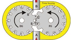
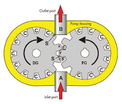
A simplified cut-away diagram of a conventional external-gear pump is shown in Figure 1. Gear pumps produce positive displacement, but they cannot be made variable displacement by any commercially viable means.
Its principle of operation lies in the two gears and how the fluid is delivered from inlet to outlet, as well as how the inlet and outlet ports are sealed from one another. Each gear has 12 teeth, but can be any convenient number, odd or even—it is the pump designer’s choice. The figure contains arrows that indicate the direction of gear rotation, with the powered gear (PG) turning counter-clockwise and the driven gear (DG) turning clockwise. Low-pressure fluid enters through the inlet port and is carried around the outer peripheries of both gears in the root chambers (C).
All the gear-pump action takes place at the point of mesh between the two gears at the teeth labeled x, y, and z. A seal is formed at the point labeled S, between the y and z teeth, due to the resulting torque that forces the PG tooth into the DG tooth. This is a positive, metal-to-metal seal that isolates the high-pressure outlet port from the low-pressure inlet port.
The quality of the seal is a direct consequence of the gear’s squareness and the finishes on the tooth surfaces. This mesh seal is maintained until the next pair of teeth come into play and take over the sealing function. It is a rolling type of seal due to the shape of the tooth faces, a consequence of normal gear-tooth profiles.
Meanwhile, sliding seals are formed at the tip of each tooth around the peripheries. Each tooth tip helps to seal the inlet from the outlet, thus resulting in better efficiency. In addition, a sliding seal is formed by the clearances between the gear faces and the mating stationary hosing parts. It should be clear that manufacturing tolerances for surface finishes are critical to proper function of the pump.
Pumping action takes place in the two active gear roots labeled E and F. Note that as the indicated rotation continues past the snapshot positions in Fig. 1, the volume of fluid in the E root of the PG gear is being reduced by the mating tooth of the DG gear, resulting in a positive expulsion of fluid contained therein. At the same time, the volume of the F root of the PG gear is increasing, creating a partial vacuum. This causes atmospheric pressure in the reservoir (not shown) to fill the expanding void inside the pump.
Torque action is positive, but a bit more subtle. It all takes place as a result of the seal (S) between its tooth and its mate on the PG gear. Pascal’s law dictates, for instance, that all of the fluid-carrying roots (C) have equal pressures on their teeth and therefore contribute nothing to the torque generation. On the other hand, the z tooth on DG has low pressure on its bottom side, which continues to the tip of the z tooth but reaches around to the top side only to the point of seal S.
Between S and the root of tooth z, there is high (outlet) pressure acting between S and the z tooth root. However, the entire bottom side of the x tooth is at high pressure, resulting in an unbalance of forces and creating a CCW torque on the DG and a CW torque on the PG. Interested readers are urged to study this force unbalance if it’s important to visualize the torqueing and pumping. If not, it’s only necessary to accept that the two gears do indeed positively intake fluid at low pressure and expel fluid at high pressure. Also, as pressure increases, more input torque is required to turn the pump shaft.
Fixated on Fixed Displacement
As already stated, there has been no commercially viable variable-displacement gear pump. Only fixed-displacement gear pumps survive the ravages of the competitive marketplace. They are popular, especially in the United States, primarily due to the fact that energy costs are relatively low compared to other countries.
Gear pumps have benefited from continued improvements in both design and manufacturing methods, resulting in higher continuous operating pressures. A number of currently available gear pumps can operate reliably at more than 200 bar (about 3,000 psi). However, efficiency issues are discouraging in light of today’s emphasis on energy conservation.
The pumps themselves feature remarkably high power efficiency, but to get variability of output flow and variability of actuator speed, valves are necessary to bypass and throttle flow. Recall that a fixed-displacement pump operation is essentially a constant flow process, regardless of load pressure. The pump must be selected (select a pump with the required displacement) and its speed set in order to reach the highest flow required of the load. That’s because at intermediate load conditions, the pump produces too much flow and must be diverted through a bypass function.
Bypassing some of the pump output, while at the same time throttling flow to the load, is a notoriously inefficient process. Greater efficiency can be gained with variable-displacement pumps since they eliminate the throttling valves. However, implementing variable-displacement pumps with an unequal area (single rod end) cylinder poses its own set of challenges, which will be addressed in the next article.


