This file type includes high resolution graphics and schematics when applicable.
Alternators are ac generators. They convert mechanical power into alternating-current electrical power. The term generator creeps into the language of ac circuits and systems. Technically, though, the term generator is reserved for dc power generation, while alternators apply to ac power generation. On the other hand, there is NO confusion when people refer to alternators as “ac generators,” so indignation would be misplaced when using that term, even in polite conversations.
All electrical generating devices will function as either generators or motors. This is true of both ac and dc machines, but the discussion here concerns ac devices. If the synchronous motor (Fig. 9) described in last month’s article (Part 2) was powered mechanically through its shaft and some load, say, a light bulb, was connected to one of the phase coils, the bulb would glow given that there’s enough mechanical power available.
The alternator relies on Faraday’s EMF law. The spinning rotor field “cuts through” the stator coils and their relative motion induces a voltage. Figure 2 from Part 1 of this discussion (April issue) depicted a machine with its rotor magnetized and spinning counter-clockwise. A vertical coil generated a cosine wave, while a horizontal coil, when rotated, generated a sine wave. In other words, it was a two-phase alternator. It could be used as the two-phase ac power source for the aforementioned motor.
In the motor, the rotor lags behind the stator field rotation. Energy is converted from the electrical realm and converted to torque and speed to drive a mechanical load. In the alternator, the mechanical input power causes the rotor to get ahead of the stator field. As a result, energy is delivered from the torque and speed and converted to voltage and current power out of the electrical coils.
An interesting thought experiment is to ponder the actions in one of the power company’s many windmills dotting the countryside. When the wind blows with sufficient power, the windmill blades convert the aerodynamic energy into mechanical energy, which then turns the alternator shaft to generate ac voltage and current. The rotor will be leading the stator field.
Consider, though, what would happen if the wind died down and didn’t act on the windmill blades (called “sails” by those engaged in wind energy harvesting). Under such a condition, there’s no torque on the rotor. However, if the machine is still connected to the power grid, other alternators, such as those powered by coal-fired furnaces and boilers, would supply electrical power to the machine. Thus, it would operate as a motor, powering the sails mechanically and turning the machine into a big fan. In low-wind conditions, therefore, the windmill must be electrically disconnected from the greater electrical power grid to prevent energy flow into the fan.
Large capacity synchronous motors (e.g., those rated at more than a few kilowatts) don’t use permanent magnets for their rotors. Instead, they incorporate electromagnets, which necessitates the conduction of some electric power into the rotor via slip rings and brushes. Slip rings are simple conducting rings that attach to, and spin with, the rotor, but are electrically insulated from the machine shaft.
Each coil has two slip rings to carry current in and provide for the needed return path. They are in intimate, sliding contact with stationary conducting brushes, often made of graphite due to its electrical conductivity and its low abrasion, while continuously rubbing against the slip rings. The brushes and slip rings allow an electrical connection between the rotating world of the rotor and stationary external world.
Alternators are used in all modern automobiles, trucks, and other mobile equipment. They have become practical since the 1960s due to the development of large-capacity, reliable, and inexpensive diodes to convert the alternating current into direct current. Most automotive alternators are of the three-phase variety.
Induction Motors
The most ubiquitous type of motor is the induction motor, which can be found in homes and industries across the world. They take advantage of the rotating field created by the stator windings, as is the case with the synchronous motors, but with a less-complex structure. Induction motors are to the electromechanical world what hydraulic cylinders are to the hydromechanical world. They differ in their motion; the former produces rotational motion and the latter produces linear motion.
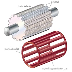
Given that the induction motor uses a rotating field for its ultimate propulsion, its stator will be similar to that of the synchronous motor, except that it will most likely be three-phase, not two-phase. Regardless, the rotor construction consists of a series of ferromagnetic laminations mounted on a shaft (Fig. 10). The laminations are electrically isolated from one another with lacquer or varnish coatings to minimize eddy-current heating in the iron.
The term “squirrel cage” comes up because of the way that the rotor conductors are arranged. The isolated conductor cage is also shown in Figure 10. In the final rotor assembly, the individual conductors will be inserted into their respective slots in the laminated rotor.
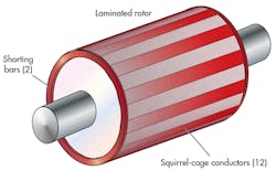
In the rotor pictured, 12 conductors are in the squirrel cage and 12 slots are in the laminations to receive the conductors. When assembled (Fig. 11), the composite rotor is round and generally quite smooth because the conductor cage surrounds the laminations and helps hold the assembly together. The conductors are held together with shorting bars on each end of the cage. In the functioning motor, currents are induced into the rotor conductors. The currents are allowed to “circulate” by virtue of the shorting bars.
The rotating stator’s magnetic field penetrates and exits the rotor radially and approximately, in line with the stator field’s central axis as shown in the synchronous motor (Fig. 9, again). In the induction motor, the field’s rotational motion is transverse to the squirrel-cage conductors, and the relative speed between the two results in an induced voltage. The induced voltage causes a current in the very-low-resistance squirrel-cage conductors; that current can be very high because the rotor shorting bars enhance the current buildup.
Once the polyphase stator is energized, the field immediately accelerates to synchronous speed. The rotor, with its iron laminations and attendant inertia, is stopped. The relative speed reaches high levels, inducing a high current in the rotor conductors. What’s interesting is the induced rotor current creates its own magnetic field of 90° displaced from the rotating stator field, resulting in a very high torque on the rotor. The rotor quickly accelerates, trying to catch up to the spinning stator field, i.e., synchronous speed, no matter the amount of poles. Polyphase induction motors have a natural ability to start because of the torque created when the rotor and rotating fields maintain different speeds.
This file type includes high resolution graphics and schematics when applicable.


