This file type includes high-resolution graphics and schematics when applicable.
Several different types of internal gear pump designs exist, but only the gerotor (contraction of the words, “generated rotor”) has achieved wide commercial adoption in hydraulic fluid-power applications. Early attempts date to efforts by Galloway in 1787, with others adding to its development in the intervening centuries. W. H. Nichols was the first to develop gerotor mass-production techniques back in the 1920s. Eventually, a family of pumps and motors grew up around the basic gear set.
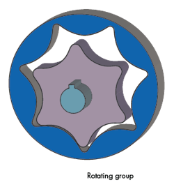
Figure 9 shows a basic gerotor gear set in three dimensions. An outer gear has one more lobe than an inner gear—an essential feature to the function of the pump. A shaft connects the rotating group to an external prime mover via the inner gear element. Both the inner and outer elements rotate, but do so around non-concentric centers. The eccentricity, along with inner gear tips that self-seal against the outer gear contours, provides the pumping action.
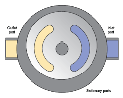
As with all pumps, the inner rotating parts are nested in a close-fitting, stationary body (Fig. 10). The yellow outlet port is hydraulically connected to the yellow internal kidney port, while the blue inlet port is connected to the internal blue kidney. The blue port delivers low-pressure fluid into the expanding gerotor set chambers, and the yellow port carries the positively expelled output flow.
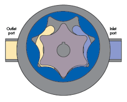
When the gerotor set is installed in the body (Fig. 11), visualize that the rotating gear set is turning, say, CCW. The inter-gear chambers in communication with the blue kidney are thus expanding, causing a pressure reduction (partial vacuum) so that external atmospheric pressure pushes fluid into those expanding chambers. In contrast, the chambers in communication with the yellow kidney are decreasing, positively expelling fluid to emerge from the outlet port. This is a clear case of positive displacement at work.
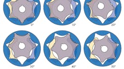
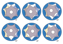
Figure 12 illustrates the relative positions of the inner and outer gears in a gerotor pump. Recall that the blue kidney port is the inlet and the yellow is the outlet. At whatever angle the gerotor is positioned, the design of the outer gear is such that the lobes on the inner are always in near contact with the inside contours of the outer gear.
This near-contact forms a sliding seal and creates expanding and contracting trapped chambers. The chambers expand when in communication with the inlet kidney and contract while in contact with the outlet kidney. In this respect, it’s very much like the vane pumps. The gerotor pump is necessarily fixed displacement.
Like most pumps, the gerotor element is fully capable of functioning as a motor. With the exception of somewhat higher power density, gerotor motors hold no special advantage over spur gear motors.
A variation from standard construction results in a very large effective displacement in a very small package. The idea uses an outer gear that does not rotate, but is locked to the body. The rotor rolls around inside the outer gear and is said to orbit because the centerline of inner element varies with rotation. To couple the varying internal center of rotation with an external shaft that has a fixed center of rotation, an internal shaft, referred to by some as a “dog bone,” must have a double universal joint.
The motors also must be equipped with a rotating port plate to replace the fixed kidney ports. That’s because the various gerotor chambers change from pumping to absorbing, depending on the inner element’s orbit position. These motors are considered low-speed, high-torque (LSHT) designs. The orbiting inner rotor produces an internal equivalent gear reduction.
More detail on this motor type is beyond the scope of this brief summary of electric-hydraulic analogies. Interested readers should refer to the many fine tests that explore the function and characteristics in greater detail.
Looking for parts? Go to SourceESB.
This file type includes high-resolution graphics and schematics when applicable.
