Many coal powered electric generating plants receive their coal via river barges. The barge pulls into a lock, and a large vertical conveyor with multiple rectangular buckets is lowered into the front of the barge to unload the coal. To remove the coal from the barge, the conveyor is lowered until it reaches the bottom of the barge. A cable attached to the front of the barge then pulls it forward while the vertical conveyor continues to transfer the coal to a horizontal conveyor system.
When the vertical conveyor reaches the end of the barge, it raises and moves sideways. Then the barge drifts back to its original position, and the process of removing the next row of coal starts again. The barge is completely emptied in four back-and-forth passes.
We were called into a plant having a problem with the cable system that pulled the barge forward and then allowed it to drift back to its starting point. Several hydraulic motors failed from the system overheating, some from what looked like cavitation damage and continuous seal leaks.
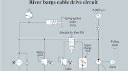
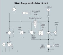
The hydraulic circuit for the cable drive is shown. It has a pressure-compensated pump with a safety relief valve to limit pressure spikes. Plant personnel found the safety relief setting was set too close to the pump’s compensator, which created some of the heating problem. They adjusted the pressure setting to 150 psi higher than the pump, but the overheating problem continued. After technicians replaced the motor with a rebuilt one, flow from both pump and motor case drains was measured and found to be within their acceptable range.
This system had very little information in the service manual other than a bill of materials and the schematic. They had no idea how to set any of the adjustments other than what they were told about the safety relief setting.
Any idea what they should do next?
Robert J. Sheaf Jr., is founder and president of CFC Industrial Training, a Div. of CFC Solar, which provides technical training, consulting, and field services to any industry using fluid power technology. Visit www.cfc-solar.com for more information.
Solution
The overheating coal barge problem was caused simply from the lack of documentation and instructions on how to set the different pressures.
The pump compensator was set to provide enough force to pull the loaded barge through the un-loader system, and the safety relief was set properly at about 150 psi higher to protect the pump and system from excessive pressure spikes. These changes helped lower the heating problem.
When the feed-out valve was energized to allow the barge to drift down stream, the pulling cable hydraulic motor became a pump. The cable tension valve’s pressure should be set low enough to allow the barge to drift downstream without allowing it to run away. It operated somewhat like a counterbalance valve would on a cylinder.
The drifting barge pulling on the cable caused the hydraulic motor to act as a pump. Pumps need a suction line, and providing a small supercharge of 100 to 200 psi will prevent cavitation to the pump-motor unit, extending its operating life. Another benefit is that noise is greatly reduced by having a charged suction line.
However, the supercharge flow control was set way above the amount of oil lost to leakage. The excess flow was relieving over the supercharge pressure control, generating unwanted heat. To add to this problem, the supercharge relief was set above 400 psi.
After lowering the supercharge relief to 100 psi, the supercharge flow control was set as low as possible, just above the oil leakage rate. Lowering the valve to 100 psi also caused the differential pressure across the cable tension valve to increase by 300 psi. An adjustment was made to lower its setting by this amount. The system now operates normally.
Solution to October’s gold ladle tilting problem
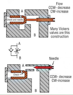
The gold ladle system circuit that used the pilot operated directional valve with pilot chokes did not have any defective components. When our Jon Rhodes arrived to troubleshoot the problem, he noticed the pilot choke adjustment screws were adjusted to the fully extended position, (fully counter-clockwise). He told them the first thing they needed to do was open the pilot chokes by adjusting the screws fully clockwise. The clockwise adjustment actually opened the chokes. The illustration shows how the check controls speed in one direction and by-passes in the other. This is not an uncommon set-up and should be considered when troubleshooting systems.


