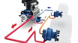
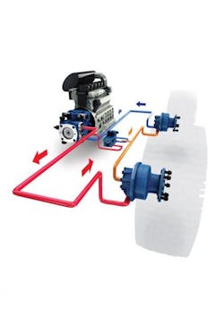
Myriad mobile machine functions exploit hydraulics technology, ranging from transit drives and swing functions to boom operation and conveyor drives. All these functions rely on a pump located somewhere in the machine to provide the power needed to accomplish the intended work. The pump’s placement within the system depends on the availability of a mechanical rotational power source to drive the pump’s input shaft (Figure 1).
Two separate base-type applications, on and off-highway, offer opportunities and distinct ways for pump-mounting locations and drive inputs. Many options are available, but keep in mind that one input isn’t preferred over another. Usually, the design envelope within which the drive designer must physically fit the pump eliminates some options — maybe even all but one. This makes it important to understand the pros and cons of each input type.
On-Highway Equipment
On-highway applications — such as concrete-mixer trucks, truck-mounted cranes, and dump beds — rely on traditional mechanical transmissions to move the vehicle. Few options exist to provide the rotational power for these vehicles’ onboard hydraulic pumps.
The hydraulic pump typically is mounted on the side of a transmission-integrated power takeoff (PTO). A PTO represents any of several methods that takes power from a power source (such as a running engine) and transmits it to an implement. The most common version involves a splined output shaft that allows easy connection and disconnection of the pump’s input shaft.
In the splined output shaft setup, the PTO is engaged and disengaged via the truck’s pneumatic system. Typically, little space lies between the PTO and the transmission axle, which brings the size and shape of the pump into play. A large displacement pump may be too wide or long for using this input area (because of interference from the axle). Therefore, it’s important to research the pump manufacturer’s options for mounting requirements.
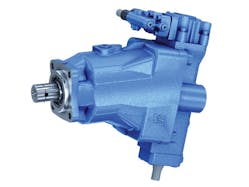
Many pump manufacturers, such as Bosch Rexroth, offer compact pump-mounting flange options or bent-axis pumps (Figure 2) that provide more clearance around the axle. Bent-axis pumps contain pistons mounted at an angle to a driveshaft, which rotates the pistons. This angle, typically around 25°, produces a compact mounting area that maintains a wide range of displacement.
Auxiliary engines (in addition to the main vehicle engine) often reside in truck-mounted applications that require full-engine power and torque. Applications such as large vacuum pumps typically use this method. In these cases, multiple pumps can populate a multipad gearbox that’s driven directly by the auxiliary engine’s output shaft. Beyond carrying multiple pumps, this configuration offers potentially greater flexibility in terms of pump size. Here, it’s important to ensure adequate power is available to the hydraulic pump to meet the performance needs of the function being controlled.
Off-Highway Equipment
Comparing on and off-highway equipment requires understanding the base design principles for each type of machine. On-highway systems usually use a conventional mechanical drivetrain, whereas off-highway equipment typically does not follow a preexisting drive chassis. Instead, it targets a specific machine purpose or activity. In these cases, designers are able to work with a blank canvas to provide rotational power from a hydrostatic transmission. Such applications usually include certain options: engine bell-housing coupling, engine crankshaft, belt/pulley, single or multipad PTOs, and pumps with built-in through drives. As with on-highway applications, no single method is better than another. Rather, each has characteristics that make it most suitable for certain configurations.
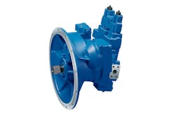
Some pump manufacturers offer bell-housing mounts for their pumps, which enable direct coupling to the diesel engine. Most of pumps driven in this manner — such as the Bosch Rexroth A11VO and A8VO (Figure 3) — are rated for high pressure. One key benefit is that they save space upon installation. Applications usually involve machines that use the hydraulic system as their only means of power for propulsion and to perform work — excavators and feller bunchers, for example. The engine power need not drive an axle, mechanical transmission, or Cardan shaft, thus conserving space.
Many times, however, space restrictions require the pump to be located away from the engine. In these instances, an engine crankshaft can couple the pump to the mechanical drive of the engine. For this type of mounting/coupling, the angle and balance of the connection method to the pump should be monitored to avoid undesired bending forces of the pump’s input shaft. It must be parallel to the engine’s crank shaft; otherwise, it will introduce oscillation to the pump drive speed that can eventually destroy the pump. It’s best to consult the pump manufacturer for the amount of allowable bending and axial forces that can be accommodated by the pump or find ways to avoid derating the pump.
Belt and pulley systems, an alternative to PTO-driven methods, are typically used when there’s obstructed access to the engine PTO or limited area around the engine. Design considerations for this type of input include the amount of power that the mechanical belt drive can transmit to the pump, and monitoring the bending moments with axial and radial loads on the input shaft. These conditions usually limit the maximum possible power transmission and, therefore, pump size.
Space Constraints
The limited space available for a single PTO from a standard engine can complicate hydraulic-pump installation. Depending on the desired pump displacement, the space required to install the pump may prevent easy mounting to the engine PTO. As a result, the manufacturer may need to use spacers or other costly add-ons to mount larger displacement pumps. Once again, it’s best to consult the pump supplier regarding space-saving options for larger displacements.
An example of a potential solution comes in the form of Bosch Rexroth’s A10VNO medium-pressure open-loop pump. The compact unit can fit into small spaces that require high displacement. Another alternative is to use two smaller pumps in a tandem/through-drive package. When combined, they’re smaller in diameter than a single, larger pump, but considerably longer.
To achieve greater flexibility in multipump applications, however, designers may consider multipad PTOs. If multiple pumps need to operate at different input speeds, a multipad PTO will provide different output speeds by changing each pad’s internal gear ratios.
Multiple pumps also can be driven by a pump’s through-drive. Most axial-piston pumps offer a through-drive option that contains a rear output shaft for driving a second pump. To accommodate different mounting flanges, through drives come in a variety of sizes — such as SAE, A, B, C, or other standards. This method can create many different combinations, but you must consider the available maximum torque levels each pump or through-drive can provide to each subsequently mounted pump. Other considerations include maximum limitations of the pump stack’s bending moments, weights, length (long assemblies may require mechanical support at the back end) and available torque limitations at each pad.
Other Factors Influence Input Choice
Even with the cases mentioned, other elements of the machine’s design should be considered when determining the hydraulic pump’s input method. For one, there’s the impact of Tier IV final emissions on machine design. Additional engine-exhaust-treatment components will occupy more engine compartment space on mobile equipment. This presents new challenges because more pumps with higher power density will be required due to space limitations. These power-dense pumps may operate at higher pressures, which could alter how the pump should be driven within the system.
Moreover, the upcoming Tier IV final engines generate a more demanding torque-ripple effect. Pumps used on direct engine drives and PTOs will be subject to higher angular acceleration fluctuation of their input shaft. Most pump manufacturers publish angular acceleration limits for input speeds.
Jay Edwards is Sales Manager, Agri/Forestry Machines, Bosch Rexroth Corp., Fountain Inn, S.C. Contact him at (864) 228-3011, or visit www.boschrexroth-us.com.


