Pump architecture and its control system are organized in view of the latest technology, but also with a healthy regard for technological limitations. The system configuration places a control computer directly on the pump housing. This computer provides a high degree of local control.
Any knowledgeable bus technologist will admit that tight servoloops cannot be reliably closed by sending feedback and error signals over the network. The problem is the uncertainty of data-transmission timing and the resulting time delays. The industry refers to this problem as bus latency. It is worthwhile to understand time limitations of buses
Bus irregularities
To use the jargon of bus experts, some buses are not deterministic. This means the time between, say, the sending of a command, and the acknowledgement that the system has responded, does not occur with repeatable time lag, even though the controlled machine has precisely the same response every time. Because of other data traffic on the bus, the bus itself inserts randomness to the data exchange process.
The Internet is an example. You can visit the same Web site each day for five consecutive days, but the time it takes for your screen to redisplay will vary from day to day. It may exchange exactly the same amount of data each time, and your computer may be exactly the same. However, other traffic on the network is random, so you see a variation in the response time of the Internet.
Field buses that will eventually be connected to our pump can be designed to have a degree of determinism. In bus-speak, determinism means that there is a fixed and known amount of time delay between communication events. Buses that use, for example, token-ring passing to gain access to the bus can have very repeatable response times from trial to trial. And scan times are reaching the low millisecond range — a noteworthy accomplishment. In spite of this, vendors and supporters recognize that absolute determinism is not possible. Perhaps more importantly, they also realize that a very-low delay time cannot be achieved, so they recommend that all tight servoloops be closed at the device. Other bus architectures and access strategies suffer from random variations between repeated events with the randomness caused by other bus traffic.
In our case, the device is the pump and all of its immediate, integrally mounted peripheral electronic gear. Displacement and pressure must be controlled, among other things, and servoloop update times must be no more than 1 or 2 msec to provide the ultimate in pump performance. To do and expect less is to relegate the control system to a role that is unworthy of its investment cost. The dedicated local processor — which the bus industry calls distributed control — will ensure that response and performance will be the best that the hardware can deliver. Sending the data back to a central processor to close the servoloops would jeopardize response and performance.
Pump performance profiles
The flexibility designed into an electrohydraulic pump offers the maximum of utility to the user. The versatility is mechanized through computer software to control the hardware already described. With the right software, several conventional pump configurations can be achieved:
• simple variable displacement,
• pressure compensation,
• power limiting, and
• load sensing (output flow control).
The conventional means for implementing these basic pump functions has been through sensing, feedback, and control in hydromechanical hardware. This will continue to be done well into the future. However, for the ultimate in versatility and control, electrohydraulic pumps will gain increased acceptance. The need for users to “talk to” and “listen to” all types of mechanical devices (including pumps) will lead to the demand for communication interfaces. This will also boost the demand for sensors and controls.
Simple displacement control
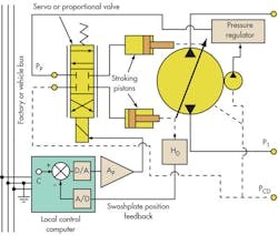
Pump-displacement control begins with the servo or proportional valve whose hydraulic output connects to the pump’s servo-stroking pistons, as shown in Figure 1. The pump-stroking pistons move to change the cam angle and, thus, change the displacement. An amplifier appropriate for the valve coil — either torque motor or proportional solenoid — electrically drives the valve.
The input to the amplifier comes from the local computer, or more precisely, from a digital-to-analog converter (d/a) that is connected to the local computer. Meanwhile, a swashplate angle transducer, HD in Figure 1, sends its signal to the computer through an analog-to-digital converter (a/d).
The a/d converter receives output from the angle transducer, converts the signal to a parallel digital value, and “places” it on the local computer chip’s internal parallel bus. (This bus is not to be confused with the serial-communications bus that will carry signals to and from the pump over the entire factory network.) As it resides on the computer bus, the value of the angular position is available to the programmer, who must provide the correct computer code to acquire it.
At this point, the programmer must know the physical port to which the angular position signal is connected in order to read the angular value. The programmer must also know where the command signal is coming from. Here is where things really get interesting. Sometimes the command will be internally generated from other control software. Other times, it will “come down the factory network bus.”
Control in mobile applications
For example, in a mobile machine — where the pump stroke may be controlled by an operator’s joystick — the command would arrive at the pump through the vehicle’s serial fieldbus (CAN, for example). On the other hand, if the pump is operating in start-up mode, there may be a software command profile that gradually brings the displacement up to some predetermined value. In either event, the programmer must know the mode of operation and, if applicable, to which port the command is connected.
For the mobile application, the command would appear on a digital input to the local computer, as handed off from the serial-bus interface. The program would:
1. read the data at the port for the command,
2. read the port for the swashplate angle transducer,
3. calculate the difference between the two, and
4. output this difference (the error) to the port that feeds the servo or proportional amplifier.
This process closes the servoloop on pump displacement. A command could be sent from the operator’s joystick, and the pump would take on the commensurate displacement. If a programmed displacement changes, such as with the scenario just described, a predetermined set of displacement values would be established — a data array. Think of this as a column of numbers stored in the local computer memory.
Upon receiving the trigger to start, the computer would read the first number in the array and use it as the displacement command. After a few milliseconds, the program would go to the array again, but read the next value, use that as the command, and so on, until reaching the end of the array. There may be as few as a half dozen different values in the array, or there could be hundreds. The more values, the smaller each command step size, and the smoother the start-up. In that way, the displacement would follow the desired path in going from the initial value to the final value. It is not a great stretch to realize that the scenario for the joystick command and the command profile are very similar. The only real difference is where the local computer looks to find the next command value.
Commanding from memory
How does the command profile get into the local computer memory? There are two possibilities: First, if the profile is known when the pump is manufactured, it can be loaded as a part of the final test on the pump. If it’s not known until application, the pump would be installed and connected to the factory or vehicle serial-communication bus.
During a configuration process, all the pertinent data involving the pump (transducers, math models for diagnostics, and all special start-up profiles) would be entered into a master computer remote from the pump computer. At the appropriate moment during commissioning, all the pump’s parameters would be downloaded from the master computer to the pump computer. All values would reside in local memory and wait for their unique command signal.
This lets the pump be operated by a joystick or a command profile. When the master computer sends a mode signal to the pump, one value would signal the computer to look to the joystick, the other value would signal it to look to the stored command profile.
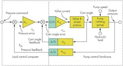
Using the mode signal concept, the pump can be made to perform as a conventional pressure-compensated pump. In this mode, if the pressure is lower than a setpoint or commanded value, the displacement increases. A command signal is sent to the controller, and if the pressure measured by the output pressure transducer is less than the command value, the error voltage is then sent to the d/a converter, then to the servo or proportional amplifier, which causes the displacement to increase. Figure 2 is an analog-style, block diagram of the pressure-control system showing the hardware and software functions as if they were all actual hardware.
Note the feedback loop within a feedback loop. The pressure loop is “wrapped around” the displacement-control loop. It’s not a disturbing situation, but it creates a problem that may not be immediately apparent: the control law for the system does not produce a pressure-feedback signal equal to the command signal. Error exists in the pressure control that is caused by the displacement-feedback loop.
To understand this problem, consider the situation where the system is operating in steady state: constant output pressure and shaft speed, and the load flow is constant and moving some load. This situation requires the pump cam angle to be constant. If the cam angle is stationary, then the servo or proportional valve must be centered. With the valve centered, the current must be zero — meaning that the cam angle error signal in Figure 2 also must be zero:
εCA = 0 = (AP × εP) – ƒCA,
where εCA = cam angle error, AP = gain of the pressure error amplifier (software), εP = pressure error as indicated in Figure 2, and ƒCA = feedback signal from the cam angle transducer.
But pressure error can be expressed as:
εP = PC × PFB,
which can be substituted into the first equation:
εCA = 0 = (AP × PC – AP × PFB) – ƒCA,
Solving for the feedback pressure, which is a measure of the actual output pressure, we get:
PFB = PC – ƒCA/AP,
which is the important form of the final steady-state control law.
First, the preferred control law would be one with the ƒCA term equal to zero. Therefore, the actual (feedback) pressure would be the same as the commanded pressure. However, because the ƒCA term is not zero, it causes the actual output pressure to be less than the commanded pressure, which may or may not be tolerable.
The system can be recalibrated so that the commanded pressure always exceeds the actual pressure, and the command from the operator can be rescaled to be essentially invisible to the operator. Also, the dynamic response of the system may be enhanced using the configuration of Figure 2. However, just as with hydromechanical pressure compensation, the load flow affects output pressure, no matter how much the program changes with the command signal. Again, this may or may not be tolerable. The performance should not be worse than with a conventional pressure-compensated pump.
Also note that the cam-angle feedback signal is divided by the gain of the pressure-error amplifier. So as the gain increases, the error contribution diminishes. As with all feedback systems, too high a gain forces the system into sustained oscillations.


