In continuous casting of flat steel, a hydraulic mold oscillator (HMO) often is used to oscillate the steel casting mold. For the HMO system to deliver consistent steel quality, its fluid must be monitored and controlled to ensure that its contamination level meets system requirements. Previously, the usual solution was a filter system that ran continuously. A new approach now being used by the EZDK-EZZ-Dekhila Steel Company eliminates continuous oil filtration by incorporating online monitoring of oil contamination level and controlling it with an external filtration unit. This approach lowers electric power consumption of the filtration unit and increases its service life.
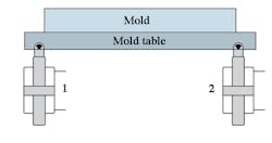
The HMO mechanism uses two electro-hydraulic servo cylinders (1) and (2) (Fig. 1), to oscillate the steel casting mold (3). The two cylinders are driven by hydraulic servo valves, one valve for each cylinder. Among the parameters that influence the performance of the HMO system is the oil contamination level of the cylinders and valves.
1. A hydraulic oscillator system uses two electrohydraulic cylinders to vibrate the mold used in continuous casting of flat steel.
To maintain optimum performance, oil contamination level must be monitored and controlled by an effective oil filtration unit. While continuous filtration had been used successfully by EZDK, increasing costs of electrical energy led the company to seek a new approach. Its new system consists of an on-line particle counter with an electronic interface signal, an intermediate control system, and a mobile oil filtration unit.
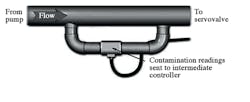
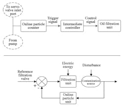
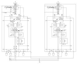
The on-line particle counter’s sensor is connected in parallel with the pump delivery line that supplies oil to the servo valves (Fig. 2). It samples and analyzes contamination of the delivery flow, and if the recorded contamination exceeds the permissible levels stated in the ISO 4406 standards, it automatically triggers a signal to the intermediate control circuit. This signal starts the filtration unit, which runs until the triggering signal from the online particle counter ceases. This integrated solution maintains the oil cleanliness level required by the HMO system and decreases the running hours of the filtration unit, which extends its service life. Diagrams of the system are shown in Fig. 3.
2. An online oil contamination sensor sends readings to an intermediate controller that signals the filter to operate when contamination levels exceed desired standards.
3. Diagrams show the layout of major system components and details of the monitoring and filtration system.
HMO System Details
The HMO system itself has an oil tank capacity of 3 m3. Hydraulic power is provided by three axial piston pumps, each with a volume of 125 cm3/rev, running at 1,450 rpm, as well as one circulating screw pump with a volume of 132 cm3 /rev, running at 1,500 rpm to provide filtration and cooling. The pump delivery line is equipped with one 32-l accumulator and two manifold blocks mounted on the servo cylinders that oscillate the mold mechanism (Fig. 4). Each servo cylinder is driven separately via a three-stage hydraulic servo valve.
4. The HMO mechanism incorporates two manifold blocks mounted on the servo cylinders that oscillate the mold mechanism.
The main hydraulic system is limited to a maximum pressure of 31.5 MPa by a relief valve. Oil supplied by the pump is filtered through a high-pressure 10 μm filter. The pump delivery line includes a check valve, a shut-off valve, and an unloading valve adjacent to the accumulator. Filtration for the HMO hydraulic system includes the twin inline filter unit for the main circulation system, a pressure line filter mounted directly in each pump delivery line, and the return-line twin filter unit. In addition, a 3 µm filter is located before the two servo valves.
Contamination Sources in the HMO System
Contamination in the HMO system can come from both external and internal sources. External contamination includes dust and fibers that enter the system when parts such as hoses and valves are exchanged during routine maintenance. Internal sources of oil contamination result from wear during the normal operation of moving components such as axial piston pumps and servo cylinders. Main wear elements typically found in this system include copper, chromium, iron and silicon, with average concentrations of 35, 24, 29, and 22 ppm, respectively.
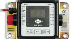
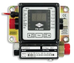
Online Particle Counter—To measure and quantify the number of solid contaminants in the hydraulic oil, the monitoring system incorporates a HIAC PM4000 online particle counter (Fig. 5), a laboratory-accurate instrument suitable for use on-site. It utilizes mineral oil as the operating fluid in the HMO and operates based on the principle of light extinction, in which a laser beam passes through the fluid and lands on photodiodes. When a particle passes through the beam, it reduces the amount of light received by the diodes. From this change in the amount of received light, the size of the particle can be determined. The particle counter has an alarm limit setting based on ISO codes for each particle size, and its alarm LED is activated when this limit is exceeded.
5. In this online particle counter, when a particle passes through a laser beam that lands on photodiodes, it reduces the amount of light received by the diodes and determines the size of the particle.
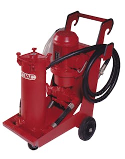
Mobile Filtration Unit—The system’s HYDAC OFU10 external mobile filtration unit (Fig. 6), has a constant displacement pump that runs at a speed of 1,500 rpm and has a flow rate of 100 l/ min. In one filtration cycle, it can filter all 2,000 l of oil in the 3-m3 HMO reservoir in about 20 minutes. The filtration pump cycles the oil through a 5 µm filter before returning it to the HMO reservoir.
6. In one 20-minute filtration cycle, the system’s mobile filtration unit can filter all 2000 l of oil in the HMO tank.
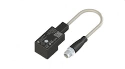
Detection and Trigger System—The detection/trigger system is activated by data recorded by the online particle counter, which causes the alarm LED to flicker when the contamination level exceeds the ISO-coded programmed limits. To employ the alarm for contamination detection, a controller with dedicated logic must be interfaced with the particle counter. If the number of pulses exceeds the normal start-up number, the controller will send a trigger signal to an external relay that activates the filtration unit for a period of 20 minutes. Afterward, the controller sends a reset signal to stop operation of the filtration unit and reset the particle counter alarm.
Prior to the new monitoring and filtration system, the company used an external filtration unit connected to the hydraulic tank, which ran continuously. Oil samples were tested regularly to determine the oil cleanliness level, but this approach resulted in excessive power consumption and accelerated degradation of the filtration unit. The new system controls operation of the filtration unit based on monitoring by the on-line particle counter to determine when the contamination level reaches a set limit.
This has proved to be more effective than off-line monitoring combined with maintenance procedures based on periodical physical sampling and analysis. Power consumption has been reduced by approximately 96 % and monthly unit service time cut by 680 hours. Tests carried out on the HMO hydraulic system have confirmed the high reliability of the filtration/on-line monitoring device.
Taher Salah El-Din, Karim El-Gewily, and Mohamed El-Shafie are with EZZ Steel Co., Alexandria, Egypt, the largest independent steel producer in the Middle East and North Africa. This information has been excerpted from a technical paper presented at the 11th IFK (International Fluid Power Conference) held March 19 to 21, 2017 in Aachen, Germany. For more information, visit ifk2018.com.
