A multitude of specifications can be selected when certifying hoses and other hydraulic components—from a simple proof set up to the most sophisticated test requirements. Each segment or product has its own set of standards and these norms are constantly under either revision, implementation or being created when new material or innovative applications become a reality.
The widespread use of a product usually requires a set of standards to accompany it. Automotive, aerospace, industrial hydraulics, and most recently CNG applications, can be listed as some of the more complex hose tests. Traditional testing concepts must give away for more effective testing procedures, as well as the fact that other testing parameters are also to be measured. This is especially true when the complexity of a thermostatic impulse testing of hydraulic hoses is required.
When a thermostatic environment is combined with an Impulse Test, new testing parameters have to be measured and a new set of variables must to be taken into the equation. Another factor that has to be deeply analyzed is how the specs define the test procedure. Sometimes even the specs are not as forthcoming as one would wish and the interpretation of which may require further investigation.
There are some international standards largely covering impulse test stand with a thermostatic chamber. For instance, in aerospace, the SAE standards, AS series has some publications dedicated to testing of coupling, fittings, hoses, and tubing assemblies. Besides demanding impulse tests, some of these specs require ambient temperatures either below-zero or well above chamber temperature. The test equipment has to simulate the environment in which an airplane is exposed. There are also National Aerospace Standards, which require temperatures below 0°C when running pressure cycles.
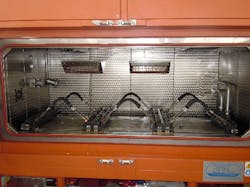
Test chamber (hot and cold)
In automotive, the scenario becomes even more complex because each manufacturer has its own set of standards generated internally by the company. In this case, for the same product and application, one test condition may be acceptable for one company and may not necessarily be acceptable for another company. This is when complexity of the test requirements makes the design of test equipment a challenging task.
More recently, with the increase of fill stations as well as in-vehicle CNG hoses, a new standard has been published. Take for instance the newest ANSI/CSA NGV 4.2 -2014 CSA 12.52 – 2014 issued in February of 2014 which focuses on testing required for the certification of such hoses. The standard required to perform these tests is basically a combination of two technologies in one unique piece of equipment.
Test Engineers’ Challenges and Metrics
This brings another set of issues for testing engineers that we could group as today’s test engineers’ challenges. This combined testing technology delineates more challenges with tighter SPECS, hose material behavior under stress, more measuring variables, and so on. They also have to decide on metrics, which would be the right measurement and locations of probes and transducers to yield the most accurate reading results. The measurement of fluid and environmental temperature under these combined conditions is a challenge. The engineers will have to decide when to reject specific measurement locations.
Current tests are far more demanding and complex than in the past. They also require easy calibration of pressure and temperature transducers. Nonetheless, the selection of the right equipment to perform these tasks becomes even more important and a substantial factor in defining the investment. New equipment that provides accurate testing results may be the solution for issues that a factory faces with outdated equipment.
Combining Thermostatic and Impulse Testing
According to international norms, an impulse test consists of subjecting components to pressure impulses with specific frequency using a fluid (usually oil) that is constantly kept at a designed temperature, typically from ambient up to 150°C. Components designed and built for automotive and aerospace markets are intended to be subjected to impulse tests—not only controlling the temperature of the fluid, but also creating a temperature-controlled ambient where test samples are placed.
According to the referring norm, the temperature of the test area where the components are tested can vary from several degrees below 0 up to 205°C ambient temperature. This ambient simulates the environmental conditions under which components work in real applications. This situation creates the need to mix impulse testing for hydraulic hoses and a thermal chamber for the ambient.
An impulse test stand runs 24/7. Therefore, the equipment requires high level of safety measures during operation. It is designed to stop automatically without presence of operator. Furthermore, it must safely contain any oil leaks and ejected particles that might occur throughout the test. Consequently, the frame of the machine must be solid and its test chamber, where the units under test will be positioned, must be oil resistant, mechanically resistant, and oil tight.
The main characteristics of a test chamber for an impulse test stand must:
- Be designed and manufactured with proper materials, resistant to high pressure and oil at high temperature.
- Contain doors large enough to allow an easy access to all areas. Also, the doors must be resistant to oil as well as ejection of metallic particles.
- Be ergonomic in order to allow operator working comfortably.
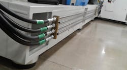
- Contain steel manifolds to withstand high pressure impulses. The manifolds must be built with suitable connections for installation of components under test. This decision must take into consideration the desired maximum achievable pressure and dimensions of components under test.
- Be equipped with manifolds capable of satisfying all these requirements and to cover a range of testing samples, with help of proper adapters.
- Allow components under test to be visible. Generally, doors should be equipped with view windows, which may introduce safety issues. Therefore, windows must contain metallic wire mesh.
- Must be capable of collecting oil spilled during tests or during removal of the test samples and to redirect this fluid back to the hydraulic system’s reservoir, possibly requiring filtration.
- The characteristics described above must remain present even in case of a test chamber where temperatures can range from below zero up to temperatures over 100°C.
Ambient Conditions
Obviously, the ambient conditions introduce additional variables. First, the frame of the test chamber and all the metallic elements subject to extreme temperature conditions must be made of stainless steel. Stainless steel has a higher resistance to oxidation, the effects of which are particularly enhanced by high temperature and humidity.
The test chamber can be described as a metallic container where heating and cooling creates few variables, such as volumetric expansion and linear expansion of the materials, as well over pressurization and depressurization.
These phenomena contribute to the stress on the structure of a test chamber. The chamber must be airtight to maintain target ambient temperature and prevent heat or cold dissipation. In addition, the test chamber area must also be oil-tight.
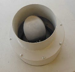
When a test chamber is heated, the volume of the air contained inside increases. This can generate an overpressure that could be harmful to the integrity of the structure. To prevent heat dissipation, a relief valve is present on the roof of the test chamber. The relief valve, which is normally closed, prevents overpressure by openinRelief valveg automatically when release of raised pressure is needed.
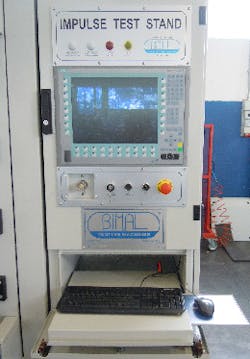
Control panel
The opposite occurs when the test chamber is submitted to below-zero temperatures. The volume of air inside the test chamber decreases and that produces less pressure. This is especially true in an air-tight test chamber, and for the integrity of its structure this occurrence is as dangerous as overpressure.
For this reason, it’s important to allow pressure compensation between the inside and outside of the testing area, during the period of temperature reduction. Note that leaving an opening, even small, between the inside and outside of the test chamber could cause ice formation.
Another risk factor connected with heating of the testing chamber is the possibility of fire hazard.
In a situation where the ambient temperature is heated up, the fluid used to execute the pressure impulses on the components under test is actually the fuel. When this fluid comes in contact with the heated atmosphere of the test chamber, there is the possibility of ignition. The hazard increases depending on type of fluid and temperature values inside the test chamber.
Theoretically, if the fluid remains sealed inside the samples under test for the duration of the test, combustion should never happen. Nevertheless, an impulse test is a destructive test and failure of a component must be considered as a high possibility.
When an impulse test stand must execute tests in presence of very high temperature conditions generated inside the test chamber, the selection of the working fluid has to be very accurate and carefully chosen.
The first criteria to analyze is the fluid’s flash point, or the lowest temperature at which a fluid can vaporize to form an ignitable mixture in air. Measuring a flash point requires an ignition source and at the flash point, the vapor may cease to burn when the ignition source is removed.
That leads to a quick consideration: If a fluid is used for executing impulse tests on components installed inside a test chamber with a temperature close or higher to its flash point, electric lights or electric devices in general must not be present. They could serve as an ignition source.
Another point to take into consideration is the fluid’s fire point. The fire point of a fuel is the temperature at which the vapor produced by that given fuel will continue to burn for at least 5 sec. after ignition to an open flame.
The last physical characteristic to consider is the auto-ignition temperature or kindling point. It is the lowest temperature at which a substance will spontaneously ignite in a normal atmosphere without an external source of ignition, such as a flame or spark. This temperature is required to supply the activation energy needed for combustion.
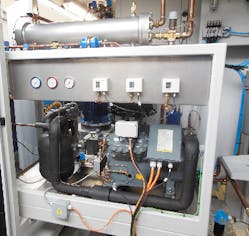
Industrial refrigeration system
The easy conclusion would be that it’s only necessary to choose a fluid with a flash point higher than the highest target temperature reached inside the test chamber. However, even this precaution might not be enough to have a safe system. In fact, when the oil spreads out during a test and hits the walls or any other hot surface inside the test chamber, the volatile part of the fluid will rapidly evaporate and the carbonaceous part of the fluid will be deposited—especially if the fluid is oil, as happens in the vast majority of applications.
That explains why the test chamber of an impulse stand is always brown and dirty. Oil residues are very difficult to remove if not scrubbed with special abrasive cleaning products. Heating continuously throughout tests, the carbonaceous residues of oil laid on the surfaces inside the test chamber lose volatility until only carbon remains. The flash point temperature of these residues is then substantially lowered due to loss of all additives that were once present.
In these conditions, these carbonaceous elements can operate like ignition sources in the case of further oil leakages inside the test chamber during an impulse test. Fresh oil coming out of the components under test can hit the same point where the carbonaceous residuals reside, and a fire can start much more easily than in its original condition.
In the market, many silicone fluids are available which are generally not considered fuels up to 300°C (572°F). These fluids do not leave carbonaceous residuals, so the aforementioned reduction of the flash point doesn’t apply for them—but compared to other fluid types, are very expensive and particularly volatile. Despite all these considerations, since safety is a primary condition for any industrial equipment, using a silicone oil could eliminate the problem of fire completely without the need of other fire prevention or suppression systems. However, the cost of the investment may be an issue, and it should be taken into consideration during the feasibility study.
There are cases, for example in military and aerospace test applications, where the fluid required by the specs (SAE AS 620) has a flash point lower than the test temperature to be achieved inside the test chamber. In this case, experience shows that a routine, reasonably priced fire suppression system would not be effective in reasonable time to make the test stand safe.
A very safe way to prevent a fire ignition is to use a system capable of reducing oxygen concentration inside the test chamber and replace it with a corresponding quantity of nitrogen, making an inert ambient inside the test area. The use of such equipment requires high level of design and manufacture of the test chamber, since any leak can jeopardize the effect of its action and consequently the safety of the test stand. Furthermore, the system must be capable of continuously monitoring the oxygen concentration inside the test chamber and communicating the safety status to the user.
Up until now, we have mainly described safety and mechanical constructive techniques. Now we should focus our attention on the heating and cooling systems that make it possible to change the temperature conditions inside the test area of an impulse machine. We will not focus on sizing, but will instead describe possible solutions and how to choose one over another.
Heating system. The easiest way to heat up the test chamber is by using electric heaters with adequate power. The power of the heaters must be accurately chosen based on the volume of the test chamber and all objects inside such as manifolds, shafts, components to test, windows, etc. One or more fans are necessary to increase heat exchange between heaters and air. Good air circulation should provide homogeneous temperature at any point inside the test chamber. The fans are another important parameter that needs to be accurately dimensioned in order to reach the target in the shortest amount of time, with the lowest power dissipation and surface temperature possible.
The surface temperature of the heaters must be of appropriate size that could be placed directly inside the test area maximizing the heat exchange. Always consider what was previously discussed regarding the flash point of the working fluid. Otherwise, if the fluid has a “low” flash point, two solutions are possible:
The heaters must be placed outside the test area and the heat exchange will occur across the walls of the test chamber. In this case, particular attention must be paid to the temperature reached by the walls inside the test area. This will negatively influence efficiency of the heat exchange. The use of aluminum can significantly improve the convection effect.
If the test stand is provided with an inert system, the fire ignition will be prevented. Heaters can be placed inside the test chamber in direct contact with air and oil.
The heating process shall be subject to a very accurate control in order to prevent temperature overshoot, since it is very dangerous for the structure of the test chamber. They are usually designed to resist up to the maximum declared temperature. A closed-loop control system is typically the best solution to hit target temperature, even though the test setup can be quite demanding. This is especially true in cases of very small or very air-tight test chambers whose heating power or fans have not been accurately assessed.
Cooling system. Generally, an industrial refrigerating system is the best way to achieve the result. The key element of these industrial systems is the compressor. It is the first and most important component and provides the overall performance in terms of temperature down gradients and stability of the system. The systems will greatly depend on how accurate the compressor was calibrated during design. The industrial refrigerating system can be either single- or multiple-stage, according to below-zero temperatures that must be achieved.
Relief valve
A reliable test can be achieved with a balanced combination of individual systems on a thermostatic stand: heating system, cooling system, and the impulse test stand. All are Not necessarily present at the same time, since some specifications require only cool temperature tests and others ask for a specific hot climate. When low as well high temperatures are required, the heating and cooling system must work in perfect harmony. Furthermore, many physical qualities must be kept under control: test pressure, test oil temperature, reservoir temperature, air temperature inside the test area, and others.
A centralized management system with a capable algorithm is required to keep each of the numerous activities in balance, guaranteeing reliable operation of the test stand. This system also monitors performance of each individual activity—upper and lower limits, as well as safety parameters.
Employing multiple systems with different management logics would be far more complex to integrate and manage. For instance, an alarm condition for the impulse test may not be the same for the heating system. In this case, the stand would halt impulse cycles and not necessarily would prevent the heating system to continue running. Furthermore, each individual system requires different settings, and in the worst-case scenario, control panels of each system would be different and located in places around the equipment or the working area.
The best design for such complex and demanding equipment is to have all of the equipment features and accessories integrated in a unique management system. All the analogic and digital signals from transducers and switches, necessary to operate it safely and efficiently, should be connected to a centralized management unit. Either by a PLC or a Compact Rio unit, this would create a reliable device capable of guaranteeing high level of safeguards and stability over time.
They also would be the unit responsible for monitoring the overall situation of the machine and to quickly intervene in case of deviation of the specs or malfunctioning of any component. This unit would also remind the operator of the maintenance schedule and time to check individual parts to help them properly maintain the equipment. Information from the test stand is always obtained from a control panel, making the operators and maintenance crew’s jobs much easier thereby reducing probability of errors.
The physical readings, provided by instruments of different systems must be available at the operator’s interface and displayed by real-time graphs that could be later acquired and saved for the testing reports and machine diagnostics.
For the equipment itself, the benefits of integration of all the systems will allow a precise setup and better control and interaction with processes to be executed. Final testing results will be better and implementation of each test will be fully automated with no intervention from the operator.
The conclusion here is that aggregating independent systems to form one equipment type is not the proper solution for this equation. Besides making managing cumbersome, this situation may increase risk of incidents in the lab area. One might consider it as a very low investment and this is probably true, but considering the ROI and the time required troubleshooting maintenance issues and programming a test, it would easily offset the initial perceived gain.
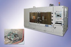
Example of a thermostatic impulse test stand
Protecting People and the Environment
All this information leads to an important aspect: the equipment selection process. There are many ways to design a simple hydraulic circuit using a rudimentary circuit with just a pump and valve. A homemade design usually follows this concept and a handful of people may accept the testing results. Demanding companies are getting more involved in the certification process.
The standards used today are subject to updates and changes, and superseded by newer and improved versions. The question is how to define a flexible solution that continues providing the same level of testing results into the future to make the investment financially sound. Finding the optimum balance between today’s needs and future requirements is a key element on the decision process.
Let’s work to make the thermostatic impulse testing safer with prudent safeguards for operators and for the environment while observing local safety and environmental regulations to provide reliable and accurate testing results. Everyone wants a comfortable, safe, and clean environment, and it is possible to accomplish this goal.
Marco Panichi, Ing., is with BIMAL SrL, Ponte Valleceppi, Italy.
