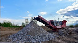
Land-clearing operations frequently process plant clippings, tree branches, and other debris by mulching. Hydraulic drives built into professional-grade mulchers deliver the high torque and dead-on speed control needed to quickly and efficiently turn such debris into a pile of mulch for composting, landscaping, or other form of recycling.
However, branches cut from the tree often must be hauled to the mulcher’s location. This may not seem significant, but consider that a mulcher can turn tree branches into a pile of chips in less time than it takes a team of workers to cut branches from trees and drag them to the mulcher.
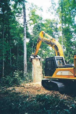
The Tree Mulcher, designed and built by Shinn Systems Inc., Concord, N.C., overcomes this limitation. An attachment for full-size excavators, the Tree Mulcher reduces trees, branches, etc., to a pile of mulch right at the work site — and requires only a single operator. It clears construction sites, utility right-of-ways, and recreational areas, and is particularly useful in wet areas or sites with limited access. Basically, it travels through an area and clears anything in its path, leaving a bed of mulch in its wake.
A clear edge over convention
Perhaps the Tree Mulcher’s biggest advantage over conventional clearing methods is that just one person can clear twice the number of trees per day as a five-person crew with chainsaws, chippers, and excavators. It also operates in wet areas where it’s nearly impossible for anyone to walk, much less clear vegetation. Depending on the model, it can clear trees with trunks up to 14 in. in diameter. Plus, an optional ripper attachment extracts the tree’s stump for subsequent grinding.
Other self-propelled grinders require that trees be cut beforehand, and stumps must be low enough to clear the machine’s undercarriage. The Tree Mulcher instead will grind stumps to 6 in. below the surface as it progresses. It leaves a 4- to 5-in. layer of mulch on the ground after clearing a right of way.
This file type includes high-resolution graphics and schematics when applicable.
One-man operation
Shinn offers several sizes of the Tree Mulcher in two configurations. The EP Series runs off the hydraulic system of a full-size excavator through priority-flow valves. The S Series, on the other hand, has its own hydraulic power unit (HPU) driven by a diesel engine of up to 650 hp. The S Series version fits neatly onto reduced- and zero-tail swing excavators in place of the standard counterweight.
When an operator activates the S Series, the HPU’s variable-displacement axial-piston pump runs full at stroke with the engine at optimum speed. The cutter head can accelerate to its full operating speed of 1,850 rpm in just 1.28 sec from a dead stop under no load. The operator then maneuvers the front of the cutter’s shield against the trunk of the tree about 20 ft above the ground. Subsequently, the excavator is driven forward, which pushes the rotating cutter head into the trunk. The weight of the treetop causes it to fall away, enabling the operator to grind the remaining trunk of the tree down into the ground. Finally, the cutter head is positioned to grind the treetop by drawing it into the grinder.
Hydraulics
The HPUs use a Bosch-Rexroth axial-piston pump incorporating torque limiting matched to the particular engine make and model used. Torque limiting allows the Tree Mulcher to exploit the full power band of the engine. Without this feature, compensator pressure would be set to whatever pressure corresponded to the maximum power output of the engine — say, 3,850 psi for a 250-hp engine. This forces the machine to waste energy because it must operate at maximum flow and pressure.
With the torque limiter, pressure can be set to maximum of 5,000 psi. As a result, when the cutter head stalls, the pressure immediately increases to maximum and provides maximum torque to reaccelerate the cutter head. As the motor speed accelerates at the cutter head, flow through the system increases enough to achieve maximum torque output of the engine, and the limiter adjusts the pump to maintain the horsepower limit through the remainder of recovery.
The S Series Tree Cutter comes in nine standard sizes powered by engines rated from 125 to 650 hp. These engine-pump packages can produce 98 to 238 gpm of flow at 5,000 psi. The pump, electronically coupled to the engine for maximum output, has a response time of less than 70 msec.
Hydraulic power from the HPU drives one or two (depending on model) hydraulic motors that produce 722 to 2,166 lb‑in. output torque at the cutter’s hydraulic motor shaft. This is a measure of the torque applied only by the hydraulic motor itself, and doesn’t account for inertia of the rotating group.
The hydraulic motor drives the cutter drum through a jackshaft to prevent applying radial load to the motor’s shaft bearings. Company officials felt this solution is more heavy duty and reliable than an overhung load adapter. A torsionally soft shaft coupling provides additional motor-bearing protection. The jackshaft transmits power to the cutter drum through a Gates Poly Chain GT-2 synchronous belt drive.
Full instrumentation in the control cab monitors inlet suction, charge pressure, charge filter bypass pressure, system pressure, return pressure, hydraulic fluid temperature (with overtemperature warning), return filter bypass, and low-fluid-level warning. A manifold automatically bleeds air from the hydraulic system at every start to help protect the pump and motor from cavitation.
Hydraulic options include electronic pump control and an offline (kidney loop) filtration circuit. The electronic package increases longevity by ramping the pump up and down. This is a very important element in the application, because its engine can experience massive overrunning due to the flywheel effect of a 1,200-lb cutter head during shutdowns. The ramp controls take the activation and de-activation of the pump to a consistent level—an otherwise impossible task for the operator.
Short-run hoses facilitate in-field replacement
Shinn created the Tree Mulcher design with functionality in mind. For example, shorter-length hoses (about 48 to 60-in. long) run down the boom, rather than one continuous hose. Although using one hose is less expensive, the nature of the operation sometimes results in stray limbs or other debris occasionally damaging the hose. The equipment often works in remote areas, and generally, the operator winds up having to replace the damaged hose (imagine dragging a 40-ft replacement hose down a right of way, crossing streams, etc.).
The company decided that the added convenience of shorter hose sections more than offsets the greater expense of using shorter runs interspersed with bulkheads. With this setup, the operator can easily remove the damaged section of hose, take it to a hose shop, and get another one made of the same length — or carry a few spares. The bulkhead has welded stops for the fittings, which prevent them from turning while replacing hoses in the field.
Another side benefit of shorter-run hoses is that they reduce movement during operation. Long hoses tend to straighten out when subjected to pressure, increasing the possibility of chafing against the boom and other components. This is particularly important with the Tree Mulcher, in which system pressure varies between 800 and 5,000 psi several times per minute.
Problems solved
When initially building this system, Shinn used an older model of axial-piston pumps. The company soon encountered the problem of pump cavitation during sudden stalls of the cutter head, which stemmed from locating overpressure relief valves in the motor — on the end of the excavator boom. Because pressure equalizes at 800 psi under no load, during a sudden stall, pressure had to reach 5,500 psi before the relief opened to complete the loop. To cure this, accumulators were installed at the front and back to provide make-up oil.
Shinn also began ordering the units with larger charge pumps. Pressure control proved to be a challenge: System pressure was set to 3,800 psi, but when plotting system pressure, the company discovered overshoots to 6,500 psi. Pressure spikes usually occur while grinding stumps. As the cutter teeth grab into the stump, large pieces of wood can be drawn up into the head, which will instantly stop the cutter drum and motor. When working at full displacement, the pump can quickly generate a pressure spike.
Loader Attachment Makes Tree Loading, Unloading a Breeze
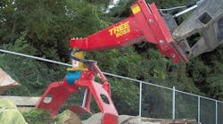
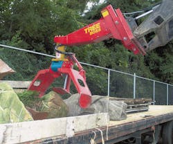
The Tree Boss, an attachment for skid-steer loaders, allows one person to load and unload balled trees. These are the larger trees dug up from nurseries that have their root balls wrapped in burlap to keep them intact and ready for transplant. A single operator can use the Tree Boss, manufactured by Tree Equipment Design Inc., New Ringgold, Pa., to do the job of an entire crew of four workers.
Hydraulic muscle
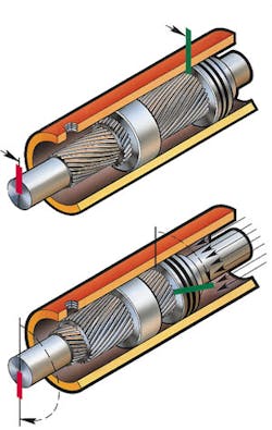
The Tree Boss utilizes three hydraulic cylinders and two helical hydraulic rotary actuators. Two cylinders operate arms that open and close to grab the root ball, and the third cylinder operates a foot that adjusts to the diameter of the root ball, providing a third contact point when grabbing the root ball. The rotary actuators work together for lifting, rotating, and positioning the tree as it’s picked up and loaded. The actuators are mounted together with their shafts perpendicular. An actuator with 25,000 lb‑in. torque capacity and 270° of rotation is mounted vertically, and one with 42,000 lb‑in. capacity and 100° of rotation is mounted horizontally.
Using two rotary actuators provides maximum articulation capabilities within the most compact configuration possible, while also generating high torque and eliminating the need for mechanical linkages. This permits a more aesthetic design, reduces weight, and holds down assembly costs. Furthermore, because trees generally must be transplanted within a narrow time window, frenzied work shifts often lead to equipment failures.
Rotary actuators hold several advantages over other rotational devices and actuator designs:
- High torque output is achieved in compact configurations.
- The shafts incorporate integral, large-diameter, drilled and tapped mounting flanges, which contribute to mounting ease and flexibility.
- Integral, extra-large-diameter ball bearings support the shaft and enable the actuators to carry heavy radial, moment, and thrust loads without the need for additional external bearing support.
- Eliminating all internal bypass and external leakage (and the nearly zero backlash characteristics) produces smooth, positive positioning without drift.
- No external moving parts are exposed.
- The helical gear design offers exceptional resistance to shock loading and abuse.
The skid-steer loader operator controls eight functions: left rotation, right rotation, tip up, tip down, grabber arms open, grabber arms close, foot in (to adjust to diameter of root ball), and foot out. An electronically controlled hydraulic valve mounted inside the boom controls all functions. The operator has access to these functions via switches integral to a handgrip that replaces the original loader’s joystick.
