As a commercial airline pilot for 20 years, I often underwent training and testing in flight simulators. I was always intrigued by these machines and wanted to build my own scaled-down version. Learning how complex and tremendously expensive these machines are offered no encouragement. Still, I felt convinced that attacking the problem by trying fresh ideas without a bunch of self-imposed restrictions, and learning from experience, would lead to a solution.
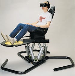
Retiring as a commercial pilot allowed me to devote the time and effort to transform my collection of ideas into a physical reality. Upon developing my first motion base, I was, of course, eager to show it off. This motion base was a chair mounted on a platform articulated by six cylinders and controlled by a joystick. Pivoting the joystick in a certain direction caused the chair take off in that direction.
My engineer friends thought the chair was uncontrollable. In their view, it had a mind of its own, but that’s what I wanted — it seemed alive. When we discussed details of the design, they wanted to see huge, complicated equations and horrendous algorithms that took everything into account. They were used to designing stiff systems for industry, with all variables tightly controlled. Naturally, they were disturbed that I ran the motion base with compressed air, because its compliance, or sponginess, does not lend itself to a stiff motion control system. The big difference between my perception and that of convention is that compliance is a power to be used rather than restricted.
To demonstrate compliance, if the motion base is powered, but no signal is provided by the joystick, the motion platform assumes a level position. If you suddenly jump onto one corner of the platform and hold on, the platform will dip, but then right itself. When you jump off, that corner rises, but the platform again quickly rights itself back to its level, equilibrium state. This is what makes the motion base seem alive. In contrast, jumping onto a stiff hydraulic or mechanical motion base would have little or no effect on the position of the motion platform.
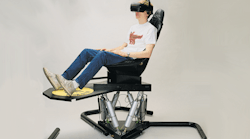
Subsequent modifications and improvements eventually led to what is now the Cyber Air Base, Figure 1. Currently, the Cyber Air Base produces 6-axis motion in conjunction with a number of audio-visual programs for simulation and virtual reality (VR) entertainment. VR is the next step beyond simulation. In simulation, you are a passenger in a predetermined journey. It’s fun and exciting, but in VR, you become the pilot or driver, not just a passenger. You control where you want to go, when, and how, so no two experiences are ever exactly the same — and they are usually unpredictable, which fits perfectly the character of the Cyber Air Base.
Vitrtual reality as an application
The reason motion bases for simulation and virtual reality attractions have been so complicated and expensive is because they have been engineered using the same technology as that applied to industrial equipment. Industrial machines need stiff systems for precise control and impeccable repeatability. Because everything is always changing in a virtual reality environment, repeatability is not as important as it is in an industrial application.
In a manufacturing environment, you want variables to be controlled and predictable. But this is a motion base for a virtual reality experience. Unlike a ride simulator, virtual reality doesn’t follow a script or repeat the same sequence of events in a program time after time. Each encounter is unique, and the person involved has nothing to compare it to except previous encounters. But that doesn’t necessarily mean he or she should expect events to occur the same way in a new encounter as they did before.
For example, if the virtual reality experience places you in the driver’s seat of a vehicle, the motion base may be oriented in a certain attitude when your virtual vehicle is at a specific location. If you move the vehicle away from that location and return to it later, the motion base does not necessarily have to be oriented exactly the same way as it was before. You probably wouldn’t have noticed or remember precisely how you were oriented at a specific location. More importantly, virtual conditions may have changed since you were at that location last time, so maybe you shouldn’t even be at the same orientation.
Not only are VR motion bases a little more forgiving of repeatability than industrial machines are, but virtual reality also does not require the tightly controlled acceleration and deceleration of industrial motion control systems. Virtual reality motion bases need only match motions that can be sensed by humans. If you have good visual effects, the human imagination fills in much of the rest, so your motion base only has to approximate the movements implied by the visual program.
A major challenge for virtual reality systems has been getting a motion base to respond in real time. We’ve been able to maintain real-time response while continually increasing the sophistication of the visual portion of a virtual reality presentation as computers become faster, more powerful, and as we develop ways of manipulating software more effectively. The dynamics of conventional motion base control has not increased at the same rate, however. Because the physical characteristics and their dynamics are unique to each application, each new application has to start almost from scratch.
This is important, because we don’t have the luxury of using the majority of our computer power for motion control. We need it for VR graphics that are becoming more three-dimensional looking and with greater detail. We can’t compromise graphics for motion control. On the other hand, we need motion to occur in real time, because we don’t want to slow down graphics just so the motion can keep up. The need to use the computer for graphics rather than motion control is becoming increasingly important as motion bases begin interacting with each other. Virtual reality is no longer an individual experiencing his or her own solo encounter in an individual motion base. We are working toward six motion bases all in the same VR environment simultaneously. Whatever one person does in his or her motion base affects what the five other individuals experience.
Simpler motion control
With servohydraulic motion control systems, the huge amount and complexity of data that must be generated, transmitted, converted, received, and ultimately executed is astounding. You wonder why they work at all, until you realize how much you’ve spent on all the high-precision components and how complicated it was to get them to work in concert. This is especially important with six-axis motion bases, because when you extend one cylinder, it affects the positions of the other five, some to a greater or lesser degree than others. With a servohydraulic system, you can’t just command a cylinder to extend without commanding the other five to extend or retract accordingly. This means motion commands must be synergistic. Otherwise, motion of one cylinder that is not consistent with that of the other five will either overload that cylinder or tend to distort the motion base platform shared by all six cylinders.
Because of their stiffness, electric servohydraulic systems are able to produce sharper motion than can be readily achieved with pneumatics. For example, if your virtual spaceship is struck by an asteroid, an electric servohydraulic system can produce a convincingly sharp impact or make the whole vehicle shudder. However, where is it written that a sensation of an impact must be generated by the motion base itself? Maybe the Cyber Air Base can’t reproduce a believable impact with its pneumatic system, but by positioning an auxiliary cylinder on the underside of the motion platform, and having the rod strike it right under the seat, I can produce the sensation of a sharp impact. This solution produces the same result an as elaborate electic servohydraulic system, but without the complexity and steep price tag.
A reality that all motion-control designers must deal with is that there are no ideal motion systems, so we must deal with compliance, deadband, backlash, inertia, and other challenges. Trying to control an ideal motion base would be complicated enough. But trying to make a motion base seem ideal from a control standpoint by factoring in algorithms for compliance, backlash, deadband, and other variables adds tremendous complexity and cost to the system. Moreover, the degree of success varies because the parameters vary — especially over the life of the application.
Instead of factoring in algorithms for compliance, so we can tackle the motion-control problem, we can rely on the compliance of pneumatics to provide the necessary forgiveness that compensates for error that may exist between the control program and the physical limitations of the motion base. To put it another way, instead of treating compliance as an obstacle to be overcome through complicated algorithms that only add complexity to the control program, we can use compliance to compensate for errors introduced by real-world conditions.
For example, one of the most elusive goals of motion control for mechanical and hydraulic systems is achieving optimum acceleration and deceleration. Getting from point A to point B in a certain amount of time isn’t as difficult as executing smooth or steep acceleration and deceleration ramps at the beginning and end of a motion profile. Pneumatics, by virtue of its compliance, has the potential for acceleration and deceleration built in. So compliance can be an asset, not a liability. Granted, the Cyber Air Base may not be able to match the ultra-sophisticated acceleration-deceleration ramps or a wide variety of motion-control profiles of a servohydraulic system, but it certainly produces believable motion — and without servovalves or even proportional valves.
Compliance and hardware
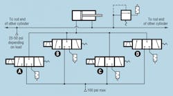
In the Cyber Air Base, compressed air flows to the cap end of each cylinder through four directional control valves piped in parallel, Figure 2. This is a six-axis motion base, so there are six cylinders and 24 valves. These are not proportional valves; basically, they are on/off type poppet valves. Response is typically under 50 msec. The valves go from fully closed to fully open in less than 5 msec, so most of the response time involves waiting for enough air to flow into the cylinders to build adequate pressure. When a valve opens, the compliance of air acts as a cushion to accelerate the load, instead of producing the jerky motion of a hydraulic on/off valve. This type of motion is similar to that produced by a soft-shift hydraulic valve
More importantly, each of the four valves is a different size. So to accelerate rapidly, all four valves shift to connect the cap end of the cylinder to pressure. When lower acceleration is needed, any combination of one, two, or three valves open. Flow is regulated by controlling which valves are open, which is determined by the software. For sake of discussion, say valves A, B, C, and Dcan pass 1, 2, 3, and 6 scfm, respectively. Therefore, we can achieve any flow rate in increments of one anywhere between 0 and 12 scfm. Opening valves A, C, and Dproduces flow of 10 scfm; opening Band Dproduces 8 scfm. Compliance is important because it creates transitions that smooth out motion as valves shift.
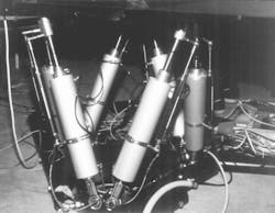
Another unusual aspect of the Cyber Air Base is that it uses double-acting cylinders, but compressed air is pumped only into the cap end of the cylinders. The rod ends of all cylinders are piped together in series, Figure 3. This greatly simplifies motion control because as one cylinder extends, air from it flows into a cylinder that is retracting. This trading off of fluid (air in this case) is inherent to motion bases, and the combined volume of air in the rod ends of all cylinders remains relatively constant, because whenever the motion platform pitches, rolls, or yaws, air exiting one cylinder is always needed by another. It also eliminates the problem of having to account for differential piston area between the opposing sides of each cylinder.
This rod-end air is held at a constant pressure in the Cyber Air Base. If this shared volume was simply open to atmosphere, gravity would be the only means of retracting cylinders. Pressurizing this volume not only assists gravity in retracting the cylinders, but adds some stiffness to the system. The magnitude of pressure is determined by mass of the load: the lighter the load (person), the higher the preload pressure — typically 35 to 80 psig. The only time this pressure requires intervention is when the motion platform lurches vertically upward or downward. This occurs when the software commands all cylinders to extend or retract, respectively. When the platform lurches upward, rod-end pressure exceeds the initial setting. This causes a pressure transducer in the circuit to open a relief valve to vent air to atmosphere. When the motion platform lurches downward, pressure drops below the setpoint, so the transducer opens a supply valve to route regulated pressure into the circuit.
VR software
The secret to accomplishing all of this lies in the software, which incorporates fuzzy logic. The fuzzy logic tackles another universal challenge in designing motion control systems — finding the optimum gain. If gain is too low, actuators will operate slowly, and precious time will be spent waiting for them to move the load to where it should be. On the other hand, if gain is too high, the actuators shoot right past the endpoint and probably begin oscillating to either side of the endpoint without ever stopping there. The software we developed uses a fuzzy-logic algorithm that essentially changes the gain of the system as needed.
A truly unique aspect of the motion control signal is that it is embedded within the video signal. It works the same way closed captioning is embedded into a video signal for broadcast or cable television. This allows conducting an interactive virtual reality experience where the participant determines what he or she will see, hear, and feel. Or you can record an experience on a standard VCR through a pair of RCA jacks provided on the side of the motion base. When you play back the tape and connect it to a sound system and video monitor, you’ll not only see and hear what was recorded, you’ll also recreate the six-axis motion program through the motion base.
Basic hardware
A 1½-hp compressor provides all the mechanical energy needed by the Cyber Air Base. Motion is introduced through three pairs of pneumatic cylinders using non-lubricated, dry air. Each 2½-in. bore cylinder is attached to a stationary base platform at the bottom and articulated motion platform at the top through stud-mounted ball joints. The configuration of the motion base is patented, but uses standard off-the-shelf components wherever possible. The angle at which the ball joints are mounted, which is also patented, offers full freedom of motion for all six axes through standard 90° ball joints. This arrangement handles load to 300 lb. We were unable to find cylinder manufacturers that offered a tapped hole in the cap end to accommodate the ball joint. Consequently, the cylinders are custom made. Another special feature of the cylinders is that the end caps are secured by retaining rings instead of tie rods or other methods. This allows quick disassembly to replace seals.
Sizing the cylinder bore turned out to be a real compromise, because you normally specify a large bore to move a heavy load. On the other hand, a smaller bore keeps the volume of air displaced manageable. Cylinders with a 3-in. bore have also been used successfully to handle loads to 600 lb. Plans for the future include using 5-in. bore cylinders with 1-in. rod end bearings to handle loads up to a ton.
Instrumentation for the motion base itself is rather simple: a linear potentiometer mounted alongside each cylinder and pressure transducers to monitor supply pressure. Electronic operator-input devices for the Cyber Air Base are more extensive and include an absolute rotary encoder for steering, linear potentiometers for the accelerator and brake pedals, and a switch for forward or reverse. The joystick is a key component, because its electronic signal is fed simultaneously to the visual program and to the motion program. Another input device is a kind of three-dimensional electronic compass. As the user turns his or her head left, right, up, down, or tilts his or her head left or right, the video image reacts accordingly.
A potential limitation is that this electronic compass cannot distinguish between when the user turns his or her head up or down, or if this motion was generated by the motion base. For example, if the operator looks up, he or she should see the ceiling of the vehicle. However, if the motion base tilts upward, the user should see a view out the front windshield with the front hood of the vehicle pointing upward. To allow the software for video to distinguish between motion generated by the user and that generated by the Cyber Air Base, a similar electronic compass is provided for the motion base. The software then compares the two inputs and generates a video image that accounts for both motions.
Potential industrial applications
With the right marriage of valves and cylinders, ¼-in. resolution can be obtained with varying loads from –30 to 300 lb. This enables pneumatic equipment to work in many different orientations relative to gravity or friction points, not just pick-and-place applications. A quarter-inch is too sloppy for most industrial applications, but is well beyond the realm of what humans can perceive in a dynamic environment. On the other hand, many industrial applications could benefit from a motion system that can react to dynamic load changes while maintaining ¼-in. repeatability — especially when the system is relatively simple, economical, and uses clean, reliable pneumatics. Repeatability should improve, but because 1⁄4in. is more than adequate for VR applications, we have not made much effort to improve repeatability beyond ¼ in.
Embedding the motion-control signal in a video signal could have direct application in the industrial world. For example, say someone uses a manipulator to position a part in an assembly operation. The software then assumes a teach function: you record the moves, edit them, and play them back so the manipulator duplicates all the moves. Signals from the joysticks could be recorded, so the manipulator could duplicate all the movements by playing back the tape. Editing errors out of the tape, optimizing movements, and playing back the tape at a higher speed would cause the manipulator to perform a task over and over, limited only by the speed of the machine.
Signals for teaching can originate from separate joysticks of from positioning the machinery by hand. Imagine using a VCR to record motions visually while you record mechanical motions. Later, you can play back the tape to watch the machine simultaneously performing the same operation. This is a simple and easy-to-understand teaching method for both people and robots.
Brad Engstrand was chairman of Virtogo Inc., Chicago, which manufactured the Cyber Air Base, when this article was opriginally published. He is now president of Motion Controls LLC, Hartford, Wis., a manufacturer of pneumatic cylinders and the InSight positioning system using QVLA sensors.
