Download this article as a .PDF
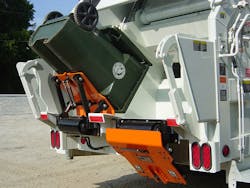
A Midwest-based original equipment manufacturer (OEM) designs and builds waste-receptacle dumpers that attach to garbage trucks, recycling vehicles, and other waste-handling equipment. The lifter is attaches to the front or side of a vehicle or onto the dumpster of a front-load refuse truck. After an operator positions a receptacle cart onto the dumper, the latter then lifts and tilts the cart, spilling its contents into the vehicle. When the dumping cycle is complete, the lifter returns to a stowed position.
Advantages of using carts and cart lifters include reduced worker compensation claims, faster route times, and larger routes, since workers don’t tire as quickly. The carts also improve street sanitation, reducing health risks by helping prevent animals from disturbing waste left outside overnight.
The helical rotary actuator (painted black) provides 220 deg. of rotation, completely emptying carts.
The heart of the lifter mechanism is a helical rotary actuator—a TorqBear Series Model T20-14E, manufactured by Parker Helac, Enumclaw, Wash. The 220 deg. of rotation produces a sharp and aggressive dumping angle that completely empties the contents of the cart. The actuator’s mounting feet with through drilled holes facilitate attachment to the lifter mounting plate: The feet are not flush with the actuator housing but, instead, are situated on the sides of the housing. This contributes to the compact nature of the mechanism by enabling the actuator to be positioned partially below the surface of the mounting plate. The through-shaft has extensions at both ends with straight spines that facilitate the easy attachment of the lifting arms—adapters with matching splines to which the arms are welded.
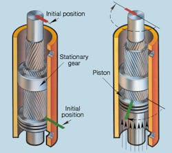
These sectional drawings show operation of a helical-gear rotatory actuator.
Actuators vs. Cylinders
The use of the actuator in its lifter designs allows the OEM to build a high-performance machine not possible with a cylinder. Actuator-equipped machines dump higher and deeper than cylinder machines. At the same time, they can be designed thinner, making access to the hopper by the operator as easy as possible.
In the illustration, the cutaway on left shows initial positions of piston (green line) and output shaft (red line). Pressurized fluid entering the lower port pushes the piston up. The stationary ring gear causes the piston to simultaneously rotate clockwise. In the cutaway at right, teeth on the output shaft mesh with those in the ID of the piston, causing the shaft to rotate clockwise relative to the piston. (The output shaft rotates at twice the speed of the piston.) Pressurizing the upper port returns the piston and shaft to their initial positions.
The long, slender configuration of the helical shaft actuators provides a clean, compact design that enables the lifter mechanism to be bolt mounted flush to the vehicle for an exceptionally low profile. The rotary actuator has no exposed moving parts; lifters using hydraulic cylinders can provide no more than 180 deg. of rotation and incorporate a more complicated system consisting of bearings, brackets, pivot points, and rods—all exposed to damage. Further, the inherent characteristics of Helac’s helical rotary actuators offer several advantages over other rotational devices and actuator designs:
- Very high torque output in an ultra-compact configuration;
- Equal torque output from both ends of the shaft;
- Shaft support provided by integral large diameter tapered roller bearings;
- Smooth, positive positioning without drift due to the elimination of internal bypass and external leakage (and nearly zero backlash);
- No exposed, external moving parts;
- A helical gear design that provides exceptional resilience to shock loading and abuse;
- Constant speed and consistent torque through the entire angle of rotation; and
- Much cleaner and more streamlined installation.
Taking everything into account, the helical actuators have enabled the OEM to design a compact lifter with power sufficient to lift heavily loaded carts.
Low Flow
A typical refuse truck’s hydraulic system operates at pressures to about 3,000 psi, with flow rates varying widely from 20 to 80 gpm. The rotary lifter uses less than 2 gpm, so a way to siphon off the correct flow was required. The lifters tap into the truck’s existing pressure line via a flow-diverter valve. This custom-made valve sends an adjustable amount of flow to the lifters and allows the remaining flow to pass through to the packer (compactor) blade.
The system has been designed to minimize backpressure, which in turn, minimizes heat and extends oil and system life. Competing OEMs use a fitting with an orifice, but those systems do not properly regulate flow (which fails to regulate lifter speed) and creates excess heat. The Helac actuator has been designed for low flow requirements, thus helping minimize oil take-off from the packer and virtually eliminating any packer slow-down.
For more information on Parker Helac rotary actuators, call (360) 825-1601, or visit the company's website.


