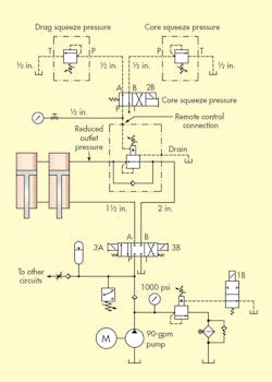
A foundry had a sand mold squeezing press that was overheating, so company officials called on Turner Hydraulics, Carlisle, Pa., to troubleshoot the problem. Turner’s technician discovered that the PLC program for the sand mold had been modified to ignore a pressure switch set to open at 1,000 psi.
Normally, the pressure switch would signal the program to unload a 90-gpm fixed-volume pump and use an accumulator to hold the mold shut until the clamping pressure would drift down to 850 psi below the pressure-switch setting. Once that occurred, the pump would re-engage and build the pressure back up to 1,000 psi.
The technician reprogrammed the PLC back to its original program, and subsequently found that the accumulator’s bladder had failed. This was probably the reason someone changed the program—to compensate for pressure problems and not realizing the real problem was a ruptured accumulator bladder.
After the technician replaced the accumulator bladder, he started the machine, and all of the functions ran fine except for two of the squeeze feet cylinders. They would not extend, and when they retracted, a gauge did not show any pressure.
The remote-control pressure reliefs for the reducing valve were located about 3 ft. from the main valve, and the ½-in. gauge line ran over to the operator station, where the defective gauge was located. The reducing valve was disassembled, and its control orifice was found to be open. Everything inspected should have worked. The pump would go to the 1,000-psi relief setting and then unload.
The original problem of overheating was caused by the pump running constantly instead of having the accumulator supply holding pressure. With that corrected, why weren’t the squeeze feet cylinders extending?
Find the Solution
Think you know the answer to this month’s problem? Submit your solution by emailing Mindy Timmer at [email protected]. All correct solutions submitted by August 23, 2016 will be entered into a random drawing for a $50 gift card. The winner will be notified, and his or her name will be printed in a future issue. Only one gift card will be awarded to any participant within a calendar year.
Congratulations to Rick Harris, CFPS, Michaelson Fluid Power, Smithfield, R.I., who correctly answered last month’s puzzler. A $50 gift card is in the mail to him.
Solution to Last Month’s Problem: O-ring Installation Causes Motor to Overload
An electric motor tripping the overloads on a hydraulic system is usually a sign that the hydraulic-system pressure increased for some reason. When we checked the valve positions in the stack, we found that someone had confused the pressure-reducing valve for the relief valve. The pressure-reducing valve closed, tending to limit its output pressure to 500 psi. However, a pressure-reducing valve does not respond to incoming pressure like that of a relief valve. Consequently, the pressure-reducing valve isolated the pump relief valve from limiting the pump’s output pressure.
Fortunately, the weak point for this system was the power rating of the system. If mechanics would have installed another larger electric motor, something else in the hydraulic system might have ruptured before the electric-motor overload tripped, causing a serious safety problem.


