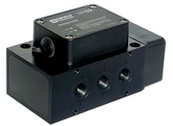
Hydraulicspneumatics 1538 Enfieldpromo

Closing the Loop on Pneumatic Drive Control

April 16, 2015
A new servopneumatic proportional control system is intended for applications requiring simultaneous high speed and high force control for positioning a cylinder anywhere along its stroke.

Pneumatics holds many advantages over other power-transmission technologies used in factory automation. These include speed, repeatability, safety, reliability, cleanliness, low potential for heat buildup, and relatively high power density. However, pneumatics is often overlooked for applications requiring closed-loop position control.

Although pneumatics is usually called on for its rapid, pick-and-place capabilities, advances in software, electronic control, and valve design may start giving other technologies a run for their money. A case in point is the S2 servopneumatic proportional control system, from Enfield Technologies, Shelton, Conn.

Enfield’s S2 servopneumatic proportional system mains control of controls heavy loads at high speeds while positioning a cylinder anywhere along its stroke.

Enfield’s S2 Proportional Control System is intended for applications requiring high speed and high force control simultaneously for positioning a cylinder anywhere along its stroke. Speeds up to 2.0 m/sec can be achieved while decelerating the cylinder to a smooth, controlled stop. Doing so prevents premature cylinder wear and damage.

The system can maintain control of masses exceeding 50+ kg masses at speeds to 0.5 m/sec (20 in./sec) by choosing an appropriate operating pressure and cylinder bore. The accompanying table shows maximum controllable speeds for six different loads and four different cylinder bores. Values in the table are based on test results from typical setup: a 250-mm (10-in.) stroke guided horizontal cylinder with 5.5 bar (80 psi) inlet pressure. Changes in moving mass, cylinder orientation or other system parameters will impact maximum speed.

The table shows maximum controllable speed using four different cylinder bores and size different load. Values are for general guidance only.

For more information, call (203) 375-3100 or visit http://enfieldtech.com.
Continue Reading

BOOK 2, CHAPTER 12: Fluid Motor Circuits

March 18, 2009
Table of Contents

Motor leakage variations

Oct. 18, 2006
affect low-speed performance

Sponsored Recommendations

7 Key Considerations for Selecting a Medical Pump

Feb. 6, 2024
Newcomers to medical device design may think pressure and flow rate are sufficient parameters whenselecting a pump. While this may be true in some industrial applications, medical...

How Variable Volume Pumps Work

Feb. 6, 2024
Variable volume pumps, also known as precision dispense pumps, are a positive displacement pump that operates by retracting a piston to aspirate a fluid and then extending the...

What is a Check Valve and How Does it Work?

Feb. 6, 2024
Acheck valve, a non-return or one-way valve, is a mechanical device that allows a gas or liquid to flow freely in one direction while preventing reverse flow in the opposite ...

The Difference Between Calibrated Orifices and Holes

Feb. 6, 2024
Engineers tasked with managing fluid flow talk about both holes and calibrated orifices, but they are two distinct entities. A hole can be any opening, but a calibrated orifice...