We have seen instances where a plant staff embarked on a significant compressed-air conservation program on the demand side, resolving issues such as:
•Identifying and repairing air leaks
•Eliminating open blowing
•Fixing malfunctioning condensate drains
•Managing all potential inappropriate uses
After successful completion of the program, the staff found that the facility was consuming less compressed air for production, but electrical-energy consumption did not go down proportionally. The reason: Without appropriate capacity controls operating correctly on compressors, it is impossible to effectively translate lower air use into lower electrical-energy input.
When working effectively, compressor-unloading controls should:
• Match air supply to demand when needed to eliminate or minimize system overpressure
• Maintain the necessary minimum acceptable operating-system pressure
• Reduce the input power cost to the optimum point proportional to the air flow demand
• Turn off unneeded air compressors and bring them back on when required
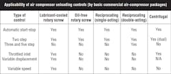
Regardless of the type of air compressor, the operating principles of capacity controls can be grouped into several basic categories. (Note that some will only perform on certain types of compressors.) The following are descriptions, as well as pros and cons, of these categories.
Automatic start-stop (AS-S)
This control simply starts and stops the electric motor or driver automatically. It can operate any type of compressor. A pressure switch usually accomplishes this function, shutting off the motor at the upper pressure limit and restarting it at the minimum system pressure.
Pro: The air compressor runs at its two most efficient modes—fully loaded and off.
Con: Most AC electric motors can survive only a finite number of starts over a given timeframe, primarily due to heat build-up. This limits the application of AS-S controls, particularly for motors larger than 10 to 25 hp.
Con: The compressor must run above minimum system pressure to hold that pressure.
Con: The system must have adequate air-storage capacity to perform satisfactorily.
Continuous-run controls (step type)
With these controls, the driver or electric motor runs continuously while the air compressor is unloaded in some manner to match supply to demand. System pressure usually commands the unloading arrangement.
Continuous-run controls can be categorized as step or modulating type.
The most common is the two-step control, which holds the compressor inlet either fully open or fully shut. Over the complete operational band, the compressor runs fully loaded (or at full flow) from the preset minimum pressure (or load point) to the preset maximum pressure (or no-load point).
At the latter, the control shuts off air flow completely. The unit then runs at no flow and full idle until system pressure falls back to the load point. Afterward, the control goes immediately to full-flow capacity. A pressure switch typically actuates the two-step control, which can be either the primary control or part of a dual-control system on virtually every type of air compressor. (Some reciprocating compressors can be fitted with 3- and 5-step controls.)
Pro: The compressor runs at its two most efficient modes—full load and full idle—which results in the lowest possible input power cost. Full idle at lowest input power is accomplished almost immediately, except in the case of lubricated or lubricant-cooled rotary-screw compressors (see “Lubrication and idling”).
Con: Both correct piping and adequate air storage are necessary to allow enough idle time over the operational pressure band to generate any significant energy savings.
Con: When two-step controls are misapplied, not only is there little or no power cost savings, but short cycling (in other words, 20 sec. on, 20 sec. off) can damage the equipment and shorten the life of normal wearing parts.
Con: Too much backpressure in the interconnecting system can cause short cycling or ineffective unloading.
Con: At 85 to 95% loads, step controls consume some extra power because they have to compress at full capacity to a higher pressure just to hold lower design system pressures.
Continuous-run controls (modulating type)
These controls match supply to demand very accurately all along the operating pressure-band range. Most incorporate some type of regulator, which in effect converts the operating pressure control band into a proportional band. If system pressure fluctuates as little as 1 psi, the modulating control immediately decreases or increases flow proportionally, depending on the signal. (This control generally is installed only on lubricant-cooled rotary-screw and centrifugal compressors.)
Pro: The minimum set system pressure draws the most power. As system demand falls, pressure rises, flow cuts back, and power usage also falls. This leads to savings at higher demand (and is the opposite of two-step unloading, in which the power draw actually increases as system demand falls).
Pro: More efficient at high loads.
Pro: Holds a relatively steady pressure when demand is stable, and responds quickly to any change.
Pro: Does not depend on storage capacity to operate effectively.
Con: Generally, there’s greater inefficiency at lower loads.
Con: Too much backpressure in the interconnecting piping can force multiple units into running on part load, when one or more could be shut off.
Controls for rotary screw compressors
Today, the industry’s most commonly used air compressor in sizes above 30 hp is the lubricant-cooled rotary-screw compressor. A significant number (80% to 85%) of these compressors use some form of modulating control as the primary unloading control, or as the upper-range portion of a dual control.
Controls for oil-injected rotary-screw compressors come in two forms: throttled inlet and variable displacement.
In a throttled inlet control, the compressor’s inlet valve is opened or closed to match supply to demand as sensed by a pressure regulator. The inlet valve modulates continuously and responds immediately to any change in the sensed system pressure. In effect, flow capacity is controlled by restricting air intake. The control holds a constant system pressure with minimal valve movement at any given steady system demand.
Pro: Smooth, non-cycling control of system pressure is easier on the power train and most other components.
Pro: Relatively efficient at loads from 60 to 100%.
Pro: Will not short cycle, regardless of storage capacity and or piping.
Pro: Simple to operate and maintain.
Pro: Usually results in lower lubricant carryover in lubricated units.
Con: Relatively inefficient at loads below 60%.
Con: Backpressure must be overcome to reach full capacity.
Con: Instant response may make the machine back down and unload, even when flow is needed for the base load.
Con: Sensitivity and rapid reaction make correct piping and backpressure control necessary for optimum operation. (This is true for all types of unloading controls.)
Variable-displacement controls for rotary-screw compressors all match output to demand by modifying or controlling the effective length of the rotor compression volume. The inlet pressure remains the same throughout the turn down, and the compression ratio stays relatively stable. This method of reducing flow without increasing compression ratios holds a power advantage over modulating and/or two-step controls in the operating range from 50% to full load.
The two most common of these unloading controls are the spiral-cut high lead valve and the poppet valve. Both methods will open or close selected ports in the compressor cylinder, thus changing the seal-off points. These ports are located at the start of the compression cycle, where pressure is very low. Opening them even a small amount prevents compression from occurring until the rotor tip passes the cylinder bore casing that separates the ports. This effectively reduces the trapped volume of air to be compressed and, consequently, the horsepower needed to compress it.
Pro: Very efficient part-load performance from 50 to 100%.
Pro: Maintains set pressure at minimum system pressure.
Pro: Very responsive.
Con: At higher loads, some units lose efficiency due to increased leakage.
Con: The mechanism is complex.
Con: Still must run two-step or modulation in lower operating range.
Variable-speed drives (VSDs) control the speed of the prime mover. In theory, the performance-unloading curve for compressors powered by VSDs is very attractive. Depending on the type of compressor, model, conditions, etc., unloading can be almost optimal in the range from 50% or 60% to 90% of load, i.e., 75% power could produce close to 75% flow.
Variable-speed turbines and engines have proved effective for years on all types of compressors. These drives maintain system pressure at the minimum set point and will immediately modulate as pressure rises in the sensed system.
In the world of electric motors, the most commonly applied VSD has been the variable-frequency driver (VFD), usually as a retrofit or part of a special package. VFDs convert 60-Hz alternating current to direct current, and then reconvert it to AC at the frequency required to turn the motor at the desired speed. This conversion usually consumes about 2% to 4% more energy; therefore, VFDs are less efficient at full load than other types of controls.
Many VFDs have been installed successfully on lubricant-cooled, rotary-screw compressor packages over the years. However, some areas of concern have limited their economies relative to cost and overall performance, particularly in retrofits.
First, the design of some rotary-screw compressors causes efficiency to drop at less than full-load speed. Second, changing speeds can produce harmonic amplification problems that were not considered at the original design speed. Third, the motor itself may have efficiency problems at the low end of the speed range, possibly because of inadequate heat rejection and cooling capacity. Compressors with air ends designed specifically for VFDs will eliminate or minimize many of these potential problems.
Another type of VSD is the switched-reluctance system. This electrical control converts standard three-phase AC power into two-phase DC. The rectified AC voltage is passed to a bank of capacitors, at which point it is increased to 600-V DC and stored. The bank then supplies the power required by each phase of a brushless motor, eliminating surge currents in the main power supply. The brushless motor has the inherent ability to survive an unlimited number of starts and stops per hour because the absence of inrush current surges keeps its operating temperature low. The true application for any compressor with a variable-speed drive is a trim machine, not the plant air system’s base-load unit.
Hank van Ormer, president of Air Power USA, Baltimore, Ohio, is also a lecturer and author. For more information, visit www.airpowerusainc.com or email [email protected]. To view or download a list of his books covering best practices with compressed air, visit bit.ly/HP1501APUSA.


