So far we have dwelt on a two-step troubleshooting process — logical mental analysis followed by hands-on investigation and correction. We have explored the three major symptoms — noise, heat, and vibration — of actual or impending hydraulic equipment malfunctions and examined at ways to rack down their causes. Now we turn to analysis of problems exhibited by specific components.
When a hydraulic system has problems, it is common practice to first look at the pump. The pump is arguably the heart of almost every hydraulic system and, as such, has traditionally been blamed for almost every operating problem. Obviously, this cannot be true, but when preliminary troubleshooting analysis focuses on the pump, a series of steps can pinpoint the specific problem and lead to the cure.
Remember that pumps do not “pump pressure.” They only deliver hydraulic fluid from the reservoir to the system. Pressure at a pump outlet is the result of some downstream resistance to flow. This is true of all pumps, but not all pumps generate flow in the same manner. Let’s begin our investigation of pumps with the two simplest design — gear and vane pumps.
The most common pump malfunctions are inadequate delivery of flow or an inability to develop required system pressure. As a matter of general interest, the failure mode differs between vane and gear pump. Most often, gear pumps lose pumping efficiency over a period of time and fail gradually. Probably, the equipment operator has noticed this slow deterioration of performance. Vane pumps, on the other hand, are most apt to stop pumping suddenly, with little or no advance warning.
The senses of hearing, touch, and sight should play in important role in the first analytical approach. The ear can easily detect the rumble of bad bearings or the distinctive ping of cavitation or entrapped air in the fluid. Our sense of touch can quickly identify excessive heat and determine if it is localized at the pump. The eye can note which components are moving and which are not — and also can read the pressure gauges installed in the system. A gauge at the pump outlet is essential for proper evaluation — and should be added to every hydraulic machine. An alternative is the portable pressure meter that connects to special couplings permanently installed in the system piping.
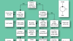
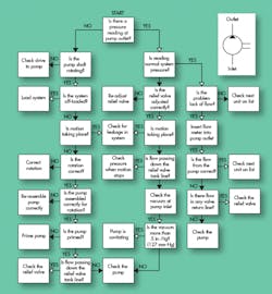
Figure 10 provides a systematic sequence of troubleshooting steps beginning with a reading of that gauge. No pressure would indicate no flow. The left side of Figure 10 addresses this situation. Note that most of these checks can be made without instrumentation. (Also note that the item on pump assembly would be a consideration only on new installations.)
If the gauge at the pump outlet registers pressure, the steps in the right-hand area of the chart should be followed. The steps require some instrumentation – vacuum gauges and flow meters. Note here that the relief valve and its setting may be at the root of many problems attributed to the pump.


