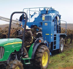
You seldom hear happy peasants singing in the vineyard as they hand-pick grapes at harvest time today. As in most agricultural operations, efficient machines have taken over the work of the harvest. However, because vineyards come in all sizes, and are planted on almost all kinds of terrain, equipment-manufacturer Oxbo International Corp., Lynden, Wash., offers a variety of harvesters, planters, and other agricultural equipment, most of which make extensive use of hydraulics.
Oxbo’s Model 316 grape harvester is designed to be towed behind a tractor. The machine straddles the vineyard’s grape trellises while the tractor’s PTO powers two pumps for two harvester functions via a double gearbox on the hitch. (Oxbo also offers a self-propelled version, the 3016 XL.) Most tractors have a 3-point hitch, which can support a cantilevered load. The Oxbo harvester connects to only the two lower hydraulic links. These links actually pull the harvester and support its front end while the wheels support the rear. With this arrangement, the PTO shaft always stays pointed at the tractor. When the tractor goes through a dip in the field, the angle of the PTO shaft will change only slightly.
The Model 316 requires a tractor of at least 75 hp. About 30 hp is used for grape picking, cleaning, and conveying. Wheel drive assist — depending upon the grades it must climb — might consume another 30 hp intermittently. In addition, a 75-hp or larger tractor has enough mass to effectively manage the 10,600-lb harvester.
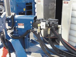
All picking functions operate from a Sauer-Danfoss 75 cc open-loop pressure- and flow-compensated piston pump. These functions include a shaker head that knocks grapes off the vine into buckets on the harvester; fans that suck leaves and debris out of the buckets to clean the grapes; and conveyors that carry them off the harvester.
The second pump is a Sauer-Danfoss 46 cc pressure-compensated unit. It supplies a very important option: a wheel-assist arrangement that powers the harvester’s wheels via low-speed, high-torque motors that bolt up to planetary-gear final drives. The wheel drives include a manual disengagement function so they can freewheel.
The wheel-assist arrangement has four functional states:
This allows the machine to be towed at speeds up to 20 mph for up to about 1 hr while moving between jobs. The PTO-driven pump does not have to be engaged.
State 2 — Wheel-assist switch in off position and wheel drives engaged. This position allows towing the harvester at speeds up to about 5 mph for a short time — to reposition it in the vineyard, for example. The PTO-driven pump does not have to be engaged, but it should be to extend motor life.
State 3 — Wheel-assist in powered mode and wheel drives engaged. This is the normal operating mode when harvesting. It allows the harvester to push itself up inclines and hills or power through mud and sand. The machine’s top speed in this mode is 4.3 mph.
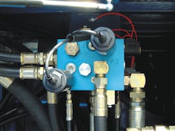
The PTO-driven pump is engaged, with its compensator set for 2500 psi. The tractor driver uses a relief valve to set drive-system pressure between 0 and 2500 psi. Electric controls automatically modulate the pressure setting of this cartridge valve. (A pressure gauge on the control panel assists the adjustment.) Because the variable-displacement pump volume defaults to full stroke, it automatically positions its swashplate to provide flow that will match the harvester’s speed to the tractor’s ground speed — always pushing with the same torque allowed by the relief valve setting. For steeper hills, relief-valve pressure can be adjusted on the fly from the driver’s seat.
State 4 — Wheel-assist in braking mode and wheel drives engaged. This allows the machine to brake itself hydrostatically while coming down a hill, so it does not push the tractor. The pump is engaged, but in this state it returns to its 100-psi standby setting. Again it strokes to provide flow to match the tractor’s ground speed automatically, but now the system pushes with only 100 psi. This provides positive flow to motor inlets, while the outlet flow from the motors is modulated through a differential-pressure sensing cartridge valve.
This normally closed, vent-to-open valve shifts only when its pilot port is vented. Another relief valve controls the pilot port. Thus, the relief-pressure setting restricts flow through the differential sensing valve — to resist rotation of the wheel motors, and thereby brake the machine.
For more information on Oxbo’s harvesters for grapes, raisins, and many other crops, visit www.oxbocorp.com.
