This article is the latest in Jack Johnson's series on Hydaulic-Electric Analogies. See the "Related" articles list below for previous articles in the series.
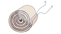
Capacitors are specified by their capacitance, most often in microfarads or picofarads for smaller sizes. The devices tend to be limited by working voltage—the maximum voltage that can be safely applied. Higher voltages could damage the separator dielectric. As the capacitance increases, maximum voltage often drops because the increased capacitance can be achieved by reducing the dielectric’s thickness.
Volume is the most important parameter for the accumulator, followed by maximum operating pressure. Because accumulators are capable of very high pressures (thousands of pounds per square inch), they can contain enormous amounts of energy that may release suddenly if not handled properly. There’s no standardized capacitance unit or evaluation method; the rule of thumb is that gas pre-charge should be about 200 psi below the nominal working pressure in the hydraulic system.
Parasitic effects
To this point, the discussion has concentrated on the deliberate forms of capacitance for both the electrical and hydraulic media. These are physical devices manufactured for their properties and deliberately plumbed or soldered into a circuit. Typically, they appear as line items in the bill of materials and on schematics.
Merely building a circuit, whether hydraulic or electronic, causes parasitic capacitances. These don’t appear on the bill of materials, but they exist nonetheless. And they can be difficult to evaluate. Such parasitic capacitances include:
This file type includes high resolution graphics and schematics when applicable.
• Parasitic electrical capacitances: A capacitance exists any time two conductors are separated by a dielectric (insulator). For instance, the cord you use to connect your kitchen toaster to the wall outlet has capacitance. In addition, every electrical trace on a printed-circuit board experiences a capacitance with every other trace on that board and every other conductor in the vicinity. This is the downside of those wonderful electrostatic fields. Fortunately, these small capacitance values can usually be ignored.
Designers of high-frequency, high-performance audio amplifiers must compensate for their parasitic capacitance, often called stray capacitance. Such compensation methods are best left to electronic-circuit designers. Stray capacitance isn’t a problem with most electrohydraulic devices, though. Or, at the least, it’s been taken care of within the electronic package. Remember that all capacitors have internal leakage through the dielectric separator. Leakage resistance is another parasitic effect.
• Parasitic hydraulic capacitance: Parasitic capacitance is more subtle in hydraulic circuits than in electronic circuits. But it also becomes a parasite when building a hydraulic circuit, and in many systems, is too significant to be ignored. This holds true in the newer, high-performance motion-control systems, especially those implementing closed-loop, feedback control. Parasitic hydraulic capacitances result from any of four conditions: fluid compressibility; plumbing or component expansion under pressure; air entrapped in the hydraulic fluid; and non-rigidity of the machine’s structure.
• Fluid compressibility: Although hydraulics is referred to as “incompressible fluid power,” it really is compressible. Compressibility is usually evaluated with the fluid's bulk modulus. Technically, this is in error, but only because the bulk modulus actually measures the incompressibility of the fluid. Sears and Zemanski discuss the material compressibility with the factor k, which is the reciprocal of bulk modulus.1 Bulk modulus in the fluid-power industry is the preferred term, which is characterized with the lower-case second letter in the Greek alphabet, β, called “beta.” In the inch-pound-second (ISO) system of units, bulk modulus is measured in “psi” and evaluated in “bar” or “megapascal” (MPa).
Consider conventional mineral oil that’s commonly used in hydraulic systems. It’s generally accepted as having a bulk modulus of about 200,000 psi. The higher the bulk modulus, the stiffer the material. Water has a bulk modulus of about 300,000 psi and, therefore, is stiffer than mineral oil. A general rule for mineral oil is that the fluid compresses about 0.5% per 1000 psi, which is consistent with a bulk modulus of 200,000 psi.
Fluid compressibility cannot be ignored in high-performance hydraulic systems. Unfortunately, that is the case, because the stypical industrial design approach focuses on steady-state performance, not dynamic. Johnson expresses the parasitic hydraulic capacitance as:2
CH =V / β
where:
CH = the hydraulic capacitance, in.5/lb
V = the total volume of fluid under compression, in.3
β = the bulk modulus of the fluid, psi.
References:
1. Sears, F.W., Zemanski, M.W., University Physics, Third Edition, Addison-Wesley Publishing Co., Reading, Mass.; 1964.
2. Johnson, J.L., Designers’ Handbook for Electrohydraulic Servo and Proportional Systems, 4th Edition, IDAS Engineering Inc., Brown Deer, WI; 2013


