When you drive under a high voltage power transmission line, your AM radio makes a buzzing noise that your FM radio does not. The reasons why are related to why an AC solenoid can burn out if it doesn't shift enough, but a DC solenoid will not. You don't need to know how or why the relationship exists if your aim is to simply replace the valve, or even design the valve, but knowing the relationships expands your knowledge continuum.
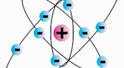
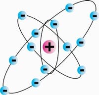
Figure 1. Research has revealed that the atom is much more complex than the Bohr-Rutherford model illustrated here. However, it will suffice to explain the analogy between electrical current, the flow of electrons, and hydraulic current (flow).
I will rely upon analogies between hydraulics and electronics, so that your present knowledge of things hydraulic can help you understand things electronic. There are many analogous concepts, but there are also many divergent ones that are profound indeed. I will cover some of both.
Atoms and molecules
In the Bohr-Rutherford (B-R) model of an atom, Figure 1, the atom was visualized as a super-miniature solar system made up of electrons with their negative charges, spinning around a much larger, positively charged nucleus, comprised of closely packed protons, Figure 1. Research has revealed that the atom is much more complex than the B-R model, but it will suffice to explain the analogy between electrical current, the flow of electrons, and hydraulic current, or, as it is more commonly called, hydraulic flow.
Unlike the planets in our solar system, which all have different masses and even different elemental concentrations, the "planets" in the atomic solar system, the electrons, are all the same. Additionally, all the protons of the nuclei are the same. In fact, every proton in the entire universe looks exactly the same as every other proton in the universe, and ditto for the electrons.
The electron and proton are extremely tiny bodies, and each has a mass, with the mass of a proton many times greater than the mass of the electron. But what sets these sub-atomic particles apart from other masses is that the electron and proton carry an electrical charge. Electrical charge, simply referred to as charge, is measurable — and the unit of measure is the coulomb. A coulomb is a quantity of electrical charge. The amount of charge in a single electron or proton is about 1.6×10⁻¹⁹ coulombs.
If we just reciprocate that minuscule amount of charge, we conclude that in order to make one coulomb of charge, we need 6.28×10¹⁸ electrons. A complete atom contains as many electrons as protons, and each has the same electrical charge, so the atom is said to be electrically neutral. Atoms can lose electrons in the normal course of their interactions, and when this happens, they lose their electrical neutrality and become ions with net positive charge.
Learning from the Bohr-Rutherford model
The B-R atomic model teaches us that the orbiting electrons, like the planets in our solar system, orbit the nucleus at different distances from the nucleus. The orbital paths for the electrons are taken to be elliptical, and they exist at ordered distances from the nucleus. Each orbit can hold only a specific number of electrons.
The B-R model also teaches us that there are two very broad categories of materials that have an impact on our quest for practical electronic knowledge: conductors and insulators. In some materials, primarily metals, the B-R model reveals that the electrons in the outer rings are very loosely bonded to the parent atom, but in insulators, such as sand and glass (silicon), the outer ring of electrons is very tightly bonded to the nucleus, that is, the parent atom. Knowing this important difference means we can now visualize a very important and practical electronic variable, electrical current.
Figure 2. A conductor is a strand of gold, copper, platinum, lead, aluminum, or other material that contains loosely bound electrons in its outer ring.
Electrical current is the movement of charged particles. Any time an electron is in motion, it constitutes a current, another measurable variable. The unit of measure for electrical current is the ampere. It is defined as the passage of one coulomb of charge in one second — the coulomb per second.
If we have a conductor, say copper wire, and we observe that 6.28×10¹⁸ electrons have gone past a point in that wire, then we conclude that there is one ampere of current in the wire. We don't actually count the number of electrons passing, instead, we insert an ammeter, an instrument for measuring electrical current, and simply read the value.
So just how do all those electrons get through that solid wire? Some fluid power specialist once quipped that he couldn't see how to get all that power through a solid wire that didn't even have a hole down the middle. That's where we turn to the B-R atomic model. The wire conductor is a strand of gold, copper, platinum, lead, aluminum, or other material that contains loosely bound electrons in its outer ring.
If we could somehow deposit an electron in one end of our wire and deposit it into one of the metal's atoms, that atom would give up an electron and pass it to its neighbor, and that neighbor would pass one on to its neighbor, and in this fashion, at the other end of the wire, one electron would have to jump out. This is how electrons pass through a solid wire. Actually, the wire is not solid at the atomic level, it is filled mostly with empty space. The conductor's atoms act like a bucket brigade and pass the electron from one to the next, Figure 2. In a complete circuit, then, the electron motion is indeed an electrical current.
On to fluids
Now, look at how this is analogous to the flow of hydraulic fluid in a fluid conductor. The hydraulic conductor has a hole down the middle, and that is its secret to success. But if we look at it closely, imagine that there is a conductor filled with an incompressible fluid. Never mind that the fluid would just dribble out the ends; allow that we can take a new, external molecule of fluid at one end and push it into the filled conductor. That molecule would push against an internal molecule, displacing it. This would displace its neighbor, and so on down the length of the tube. At the opposite end, one molecule of fluid would be ejected and leave the conductor. Thus, like a column of pool balls, Figure 3, the filled tube would transmit the motion of an incoming ball and eventually displace a ball on the other end. If the circuit is completed, then the motion of the fluid molecule, or molecules, constitute a fluid flow.
Figure 3. Like a column of pool balls, a tube filled with hydraulic fluid molecules transmits the motion of an incoming molecule and eventually displaces a molecule on the other end. If the circuit is completed, then the motion of the fluid molecules constitute fluid flow.
The mechanisms that allow electrical flow compared to those that allow fluid flow are fundamentally different. However, it is not erroneous or misleading to think of the electrical current using the pool ball analogy. In fact, such visualization may help to demystify electrical current!
Speed of light and speed of sound
This is an opportunity to discuss the time for the above described actions to take place. There are really two questions:
- What is the speed of the fluid molecule or electron as it travels through the circuit?
- After the molecule or electron is jammed into one end of the conductor, how long does it take for the corresponding molecule or electron to jump out the other end of the conductor?
Whether the medium is electronic or hydraulic, the respective answers are quite similar. In the case of the fluid system, it is common practice to calculate the fluid velocity. This is the flow rate divided by the area of the conductor, and it is normally in the order of a few ft/sec. For a given molecule to travel from the reservoir through the entire circuit and back to the reservoir, can take a few seconds to a few minutes in a typical hydraulic circuit.
Similarly, the rate at which electrons drift around a circuit is relatively slow. In a wire that carries 1 A of current and has a diameter of 2 mm, the average electron velocity is only about 0.024 mm/sec! Some observers call this the drift velocity of an electron, because it is so low. It can take the better part of an hour for an electron to make one complete circuit in a hand-held flashlight. Clearly, these electrons are not moving at the speed of light. The fluid molecules in a typical hydraulic circuit are travelling much faster than the electrons in a typical electrical circuit. To get an appreciation for electronics and the speed of light requires examining the second question.
For the second question, imagine the fluid situation and look at the pool ball metaphor. If you jam a ball into one end of the conductor, how quickly does the emerging ball pop out the other end? We could look at the physics in detail, and observe that the compressibility of the balls comes into play. However, in the end, the time for emergence of the exiting ball is governed by the speed of sound through them. The action of shoving a molecule of fluid into one end of a conductor is felt at the other end of the conductor at a time delay determined by the speed of sound in the fluid. Similarly, in the electronic case, the cause (jamming an electron into one end of our conductor) results in a different electron jumping out the other end. The time between cause and effect is governed, approximately, by the speed of light and the length of the conductor.
Making waves
What we have here are two quite different phenomena, both in the fluid case and the electrical case. The first is the drift or transport of particles through their respective conductors, while the second is the transport of a cause through the conductor. The latter is often called wave propagation. When you jam fluid into one end of a conductor, a force is required. In fluid systems, that is best visualized with pressure. The input action causes a pressure wave to travel along the conductor, and it is the wave reaching the other end that forces the emerging molecule out of the tube. Analogously, it takes force to jam an electron into a wire, and that force is best visualized with the concept of voltage. A voltage wave is sent down along the wire at the speed of light, and it forces the emerging electron out on the other end.
So, current, measured in amperes, is the flow of electrical charges, and its hydraulic analog is the flow of fluid molecules, measured in volume per unit of time, for example, in.3/sec. The actual velocity of the particles, be they electrons or molecules of fluid, is relatively low, taking minutes or even hours for a single particle to make a complete loop around a circuit. On the other hand, the motivating force — pressure in the fluid case and voltage in the electrical case — can travel about the circuit as a wave at very high velocity. For a pressure wave, the speed is determined by the speed of sound in that fluid system. In electrical circuits, the voltage wave travels at speeds approaching the speed of light. Next month, we'll explore the pressure-voltage analogy further.
Pressure compensation from a fixed-displacement pump?
Say goodbye to variable-displacement, pressure-compensated pumps. One of Jack Johnson's books introduces and explains in detail a pressure-compensated system using a fixed-displacement pump. The system does not rely on relief valves and is as efficient as a conventional system using a variable-displacement pump. An Engineering Analysis of the Pulse width Modulation Method of controlling Output Pressure of a Hydraulic Power Unit contains 128 pages of information covering complete comparative test results,. More importantly, though, you can learn how to design and build your own lowcost, constant-pressure hydraulic power units for both servo and conventional systems.
Electrohydraulic Pressure Control is the title of another publication from Johnson. This is the first book directed to the subject of electrohydraulic pressure and force control. You can learn the reasons why electrohydraulic pressure control can sometimes be a real challenge and why it is sometimes accomplished with ease. One of the key issues is when to use integral control or not. You will also learn how the nonlinearities in a hydraulic system can affect system performance and what you can do to deal with them. This book is a must-have for anyone who wants to control pressure or force, with or without electronic programmability.
Click here for ordering instructions and more information on these and other books covering fluid power and control technology.
