Economic pressures and heightened competition have machine and vehicle OEMs under the gun to improve the productivity, efficiency, and life of the equipment they build. And ways they’re meeting this demand include running machines faster and boosting hydraulic-system pressures to generate higher forces.
In a previous article (“Upping the ante on seal performance,” Hydraulics & Pneumatics, Sept., 2009) we looked at seal design considerations related to higher cylinder operating speeds. In this installment, we’ll examine how higher cylinder pressures affect seal designs. But the discussion also relates to higher energy density – systems that maintain the same operating pressures but reduce physical size, either diametrically or axially.
Material deformation, hardware dynamics, fluid-film integrity, wear, and heat all play a role in sealing system performance when pressures increase. Here’s a look at each.
Material issues
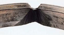
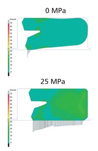
The compliant materials used for seals deflect more as operating pressures rise. Two types of movement result. One is extrusion, where material moves to a point where it protrudes into gaps in the hardware. The other is lay-down, where material conforms to the running surface and changes its footprint.
Regardless of how material deforms, it affects both the seals and cylinder. Consequences for the sealing system can include leakage, more friction, and shorter life. This, in turn, affects the cylinder in terms of:
Position control. Changes in seal friction affect the feedback loop in the cylinder and, thus, positional control.
Load capability. More leakage past the seals may prohibit a cylinder from moving the desired load.
Energy consumption. Seal material deformation can increase friction. Thus, the cylinder consumes more energy to move a load.
Cost. Severe material deformation, particularly on bearings, may permit metal-to-metal contact and damage to hardware.
Life. Seal and cylinder life are linked. Deformation that degrades sealing system performance will also limit the cylinder’s useful life.
To contend with material deformation, one step cylinder manufacturers can take is reducing the extrusion gap to provide more support for sealing system components. Another is ensuring good alignment. This minimizes the extrusion gap, so the seals do not see localized high-stress conditions. And manufacturers can design cylinders to reduce pressure at the seal, for instance, by adding a mechanical stop to eliminate constant high-pressure loading.
Seal suppliers have two primary avenues to pursue. One involves more-robust components, including changing the design to ensure a seal will not deform to the point of severely impacting performance; adding components such as backup rings to limit deformation and stress; and changing to materials with higher load capacity.
The second step revolves around lowering friction. Heat has a significant impact on seal deformation, so reducing friction will lower temperatures around the seal. Solutions include reducing seal contact stress; changing the design to allow for a different footprint; adjusting fluid film under the seal; and changing material.
Seal suppliers and cylinder manufacturers can also collaborate, say by keeping operating temperatures as low as possible. One way to do this is ensuring cylinder surface finish, rod hardness, and surface coatings suit the seal design and material. Proper finish between metal and sealing material surfaces ensures an adequate fluid film which, in turn, reduces friction, heat, and material deformation.
Another way to keep temperatures down is changing the lubrication pattern under the bearings. Adding grooves, cavities, and patterns or splitting the bearing will change the lubrication pattern. This can improve the characteristics of the fluid film on which the seal rides.
Also position sealing-system components to optimize fluid-film thickness, and reduce friction and heat. And finally, understand the potential of fluid breakdown and its effects on the fluid film thickness. See more in the section that follows.
Alignment also affects system temperature. One key is maximizing load distribution on the bearing. Extreme localized loading adds to system heat and limits life. Also understand spacing and location of the bearing relative to the seals. Unsuitable locations mean inadequate support and poor alignment, and that produces higher loads on seals and, thus, more heat.
Fluid film
Higher pressure means the fluid film must operate under more aggressive conditions. Resulting effects can include viscosity changes, fluid breakdown, dieseling, and explosive decompression conditions. Among the causes of changes in the fluid film:
• Higher pressures require valves that generate more force and possibly shift faster. This increases shear in the fluid and also generates more heat.
• Seals are energized by the fluid. Higher pressures cause the seal to put greater stress on the fluid film.
• Air ingression into the system.
• Operating conditions, including rapid acceleration or deceleration of the fluid.
The fluid film is critical in sealing systems as it directly relates to leakage control, friction, and component life. An inadequate fluid film leads to higher friction, positioning-control issues, and higher energy consumption.
It also affects seal life. Loss of fluid film due to breakdown or change in viscosity can eventually curtail life. Dieseling and explosive decompression are more catastrophic instances which also limit life of the sealing system and, thus, the cylinder.
Finally, the fluid film can affect overall cost. Inadequate fluid film lets sealing system components ride too heavily on the shaft rather than on the film and damage the cylinder hardware. Here are steps to take to ensure fluid film integrity:
• Minimize the effects plumbing and valving have on fluid viscosity changes or breakdown.
• Minimize rapid acceleration or deceleration of the fluid near the sealing system to limit the possibility of explosive decompression.
• Design the system to minimize air ingression, through tank design, filling methods, orientation or flow patterns – to minimize the potential for dieseling.
• Ensure fluid is stable, its composition minimizes chances for dieseling, and viscosity changes are limited.
• Maintain proper alignment to minimize high localized loading of the sealing system components.
• Minimize manufacturing tolerances to limit the variations a seal must accommodate in the hardware. This localizes internal stress in sealing system components
Sealing system suppliers combat dieseling through material selection. Dieseling requires higher strength materials that withstand combustion of the air. However, higher strength materials are less compliant, and that can lead to higher friction, more leakage, and more-difficult assembly – all which must be dealt with through proper design.
Explosive decompression is also dealt with in materials, but in a different fashion. Limiting a material’s ability to absorb gases, maximizing its ability to release gases, and improving the strength to resist damage are desired characteristics.
Both bearings and seals can cause viscosity changes and fluid breakdown. For bearings, the main target is ensuring that the design and material, and its location relative to the seals, will handle the pressure, provide necessary support, and aid in forming a fluid film for the seals, all while staying within the system cost targets.
For seals, the main emphasis is on materials and designs that will handle higher pressure. A secondary effort would be to reduce friction and decrease temperature near the seal. Ways of doing this include reducing seal contact stress, changing the design to allow for a different footprint, adjusting fluid film under the seal, or changing materials.
Additional actions which help ensure fluid film integrity, covered previously, include ensuring proper surface finish, maximizing load distribution on the bearing, changing lubrication pattern under the bearings, and properly spacing bearings relative to the seals.
Hardware dynamics
Higher pressures increase the potential for various hardware dynamic issues to affect the sealing system and, thus, cylinder performance. Examples include:
• Cylinder ballooning and internal hardware deformation.
• Side loading. Moving bigger loads over the total stroke imparts side loads.
• Fatigue. High-stress cycling over an extended period has a potential impact on seals and cylinder.
• Vibration/noise. With higher pressures, vibration of the cylinder may not let the seal track mating components effectively.
• Pressure buildup. Valves and plumbing may permit pressure spikes.
• Contamination. With higher pressures, contamination has greater momentum and may destroy the seals.
These hardware dynamics result from various factors such as pressure, valves, accumulators, filters, connectors, and operating conditions, to name a few. In general, these dynamic issues affect seal leakage, friction, and life and, in turn, the cylinders’ position control, loading capabilities, energy consumption, life, and cost.
Good system layout and the right valves, accumulators, and filters help minimize dynamic effects. Likewise, look at minimizing misalignment for uniform seal loading; and tighter tolerances, which minimize variations for which the seals must compensate.
Seal suppliers can also alleviate dynamic effects with sealing components that handle a wide range of tolerance conditions, including ballooning; ensuring adequate fluid film under the seal in all conditions through design, contact stresses, and seal layout; and making certain designs and materials are strong enough to handle high impact conditions. Design factors such as proper surface finish and rod hardness also ensure an adequate fluid film that lets the seal handle all operating conditions.
Good bearing load distribution helps damp noise and vibration, while excessive loads may add to the problem. Unsuitable bearing locations means inadequate support and alignment issues, resulting in higher loading of sealing components, the potential for vibration and noise, and inability of the seals to track the dynamic surfaces in all conditions.
Heat and wear
Higher pressures, if not accounted for in the sealing system design, lead to higher heat and accelerated wear. For both heat and wear, potential solutions are discussed in the previously mentioned article, “Upping the ante on seal performance.”
However, increased heat and wear caused by higher pressures, instead of higher velocities, has some unique characteristics. For example, the dynamic effect of the seal in contact with a running surface worsens with higher pressures. As many seal are pressure-energized, this causes the seal to impart greater contact stresses, leading to potentially higher friction and wear. The need to maximize cooling and ensure alignment and adequate fluid film are crucial to dealing with heat and wear from high-pressure operating conditions.
One additional item which needs to be addressed is assembly, as higher pressure can require significant design changes. For instance, higher pressures typically mandate higher strength seal designs. Higher-strength, whether by materials change, added components, or complete design changes, mean less-compliant seal materials, more seal components, and/or greater spacing between the seals. All these factors lead to less assembly-friendly conditions. Limitations in ability to deform the seal for assembly or the inability to assemble into a closed groove configuration need to be understood by the cylinder manufacturer and sealing system supplier to build a successful product.
For more information on Trelleborg Sealing Solutions, visit www.tss.trelleborg.com/us.


