Continuing our discussion of pressure compensated flow control, consider that the evolution of controls for mobile hydraulic machines has always placed levers and foot pedals at the disposal of the operator, even for machines that predated modern hydraulics. Those machines used brakes, clutches, cables, and pulleys, and the operator needed access to all the controls.
This need for centralized control within operator reach resulted in the creation of the stack valve and manifolded hydraulic circuits. Obviously, this centralized all the levers, but the design also simplified the plumbing through use of pre-drilled, and precast internal passages and simple bolttogether construction. These design issues are not a part of this discussion. Instead, I mention them only to emphasize that the very nature of mobile hydraulic control demands the operator to shift more than one function at the same time. In fact, skilled operators can simultaneously shift as many as four or even five functions at a time while maintaining good control of all the affected axes. However, considerable training and experience are required of operators to keep efficiency and productivity at their peak.
Dealing with multiple motions
Previous editions of “Motion Control” alluded to problems from shifting multiple functions simultaneously. Dealing with series connected functions can be especially surprising for the uninitiated because of pressure and flow intensifications. However, all the circuit configurations already discussed have some degree of interaction between simultaneously shifted axes. Each can present some surprises to the operator, which steepens the learning, so operator training takes longer.
Never mind that the simple manual lever controls can be replaced with sleek multi-axis, electronic joysticks. If the axes interact with one another in the hydraulic circuit, challenges can still confront the operator. All the electronics incorporated into the system cannot compensate for under-designed hydraulic circuits. Considerable time will still be needed to train new operators or to train old operators in the ways of new controls,which may exhibit previously unfamiliar behaviors.
This raises the question: Is there any means of hydraulic control that will eliminate the interactions between simultaneously shifted functions (axes)? The answer is: sort of, at least to a degree that will reduce the surprises to the operator. However, zealous salespeople may be inclined to answer with an emphatic “yes,” and for the moment, I will bask in that false sunlight, too.
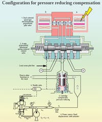
The basic circuit is shown in Figure 4, which illustrates only a single function. A two-function circuit will be discussed, but for now, the single function circuit will suffice to illustrate the principles involved.
Simply stated, the method for reducing interaction between functions is to dedicate a pressure-reducing, pressure-compensated flow-control valve to each four-way function. Cartridge configurations are preferred because of their compact size. The cartridge can be accommodated in either a subplate or a manifold with equal ease.
Laying the groundwork
Notice in Figure 4 that the power source is a fixed-displacement pump outfitted with an unloading compensator. The circuit is similar to that used by Parker Hannifin, and the four-way, electrohydraulic proportional valve is repeated here courtesy of them. I must emphasize that the circuit configuration with a fixed-displacement pump and unloader is not necessary. In fact, the fixed-displacement pump and unloader behave externally just like a load-sensing pump. However, the load-sensing pump will be less wasteful of power, especially with simultaneous operation of functions that have large load disparities — that is, when one function has a very light load (low pressure need) and another has a very heavy load (high pressure need).
The table contains descriptions of the five main parts of the circuit. There are three important facts to be stressed before proceeding with a detailed explanation of the circuit function of Figure 4.
First, the stated aim of this installment of this discussion is to explain how interaction can be minimized with simultaneous shift of two or more functions. However, the circuit of Figure 4 shows only one function. This is done for explanatory reasons, and the two-function circuit will be covered.
Second, all valves are shown in slightly shifted states, rather than the conventional method of showing circuit elements in their totally unpowered states. Again, this is done for explanatory reasons.
Third, the various parts are shown only with that detail necessary to explain the main functions, as opposed to all the construction details.
Examining the circuit
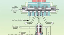
Referring to Figure 4, observe that pump output, at least in part, is directed to the radial input paths of the cartridge compensator, then emerges axially (upward) into the P port of the 4-way section, around the annulus of the 4-way body through a drilled passage, and into the central annulus of the pilot valve body.
The previously-mentioned valve shift is based on the assumption that the A side proportional solenoid has been energized — the amount is not important. The A solenoid armature pushes on the pilot spool and routes pressurized fluid into the left side end cap of the 4-way valve section. This causes pressure to build in the left end cap and forces the 4-way main spool to the right against the centering springs. Pressurized fluid then flows out the A port of the 4-way valve, as shown in Figure 4.
A subtle, but important feature of this valve system is necessary for electrohydraulic proportionality: In order to control the end cap pressure and, thus, the amount of 4-way shift, pressure feedback occurs in the pilot stage. A drilled passage connects the left end cap of the 4-way section to the B side solenoid cavity of the pilot stage. This pilot valve is called a wetted solenoid design because the solenoids are exposed to the fluid in the system.
The result is that as the 4-way end cap pressure builds, that pressure is also felt in the solenoid opposite the one being energized. The pressure acts on the end of the pilot spool. When the pressure-area force on the pilot spool end equals the solenoid force, the pilot spool centers, and end cap pressure buildup stops. The pressure in the 4-way end cap and the B side solenoid are equal and proportional to the solenoid force, which in turn is proportional to the input current to the solenoid. This explains how proportionality is achieved.
In the end, the pilot valve is merely a current-to-pressure transducer, with the amount of pressure being controlled by the amount of solenoid input current. The main spool of the 4-way section shifts a proportional amount against the centering springs.
Another subtle, but critical feature is how the load-sense pressure is managed in this valve circuit. The pressure sensing line is shown as a dashed line in Figure 4. At the left end of the 4-way spool is a slot machined around its circumference. This slot causes the load-sense pressure line to be routed to tank when the spool is centered. Recall that the 4-way spool is shown in a partially shifted position.
Additionally, small passages are drilled on each side of the 4-way’s P port. These are the load sense ports for sensing the pressure in either the A port (shown in Figure 3 last month) or the B port in Figure 4. When the 4-way spool is shifted, the sensed pressure is transmitted to the sense port (spring cavity) of the cartridge compensator.
The open end of the cartridge spool senses the P port pressure of the 4-way valve while the spring end of the cartridge spool receives the load-sense pressure. In this manner, the cartridge spool is sensing the differential pressure between the 4-way P port and the A port of the 4-way valve. The latter pressure, of course, is the load pressure.
The sensed differential pressure is also the differential pressure across the 4-way’s powered land, KVPL, the desired result. This differential pressure feedback and the cartridge bias spring work to maintain a constant differential pressure across the powered land, regardless of load pressure or supply pressure. The end result is a load flow determined essentially by the actions of other functions that are simultaneously shifted.
Moreover, the same load pressure signal that enters the cartridge’s spring cavity is also sent to one input of a shuttle valve. The output of the shuttle valve is then sent to the spring cavity of the unloading spool of the hydraulic power unit. The end result is that the pressure of the pump rises only to a level that is necessary to maintain the flow to the load on the shifted 4-way valve. Not only are we regulating load flow, we also regulate the supply pressure.
Bringing it together
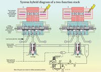
Figure 5 is the system hybrid diagram of a two-function stack. There are two nominally identical sections that are tied together by a common hydraulic power supply and a load sensing system that transmits all the sensed loads in the stack. Because they are coupled to the pump’s unloader valve spring cavity, it is only the highest of all load pressures that affects the unloading function.
The power supply pressure will always rise to meet the highest load pressure requirement in the stack. Meanwhile, the individual pressure reducing compensator cartridges are absorbing any excess pressure as they individually regulate the flow to their respective loads. This, i n a nutshell i s how an operator is able to shift multiple functions with minimal interactions between them.
|
Constituent part descriptions — circuit configurator for pressurereducing compensation 1. Pilot valve
2. Main four-way valve
3. Cartridge compensator, pressure reducing type
4. Hydraulic power source
5. Shuttle valve
|
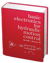
Basic Electronics for Hydraulic Motion Control
This is where your basic electronic training starts. This book, unlike many others, is written specifically by a practitioner of the hydraulic art for engineers and technicians working in hydraulics, but it teaches you all you ever needed to know about electronics. Your personal understanding of hydraulics is your ticket to learning electronics with this book, which is filled with analogies to simplify the understanding of concepts.
Everything you wondered about and need is here: transducers, interfaces, signal conditioners, pulse width modulation, controllers, amplifiers, transistors, analog electronics, digital electronics, and much, much more. It is a must read and reference for anyone interested in certification in the exploding technology of electrohydraulics.
It uses your knowledge of fluid power to help you learn and understand electronics. Order your copy now and get the book that makes electronics fun and easy to learn.
Authored by Jack L. Johnson, P.E., edited by Hydraulics & Pneumatics, and published by Penton Media, the hard cover textbook (ISBN 0-932905-07-2) contains 438 pages and sells for $39.95, plus shipping and sales tax. To order, or for more information, visit www.hydraulicspneumatics.com and click on the Bookstore button.
