Appeared in print as "Mine shaft pump switching to stand-by"
A gold mine has an elevator that travels approximately 4000 ft down a deep shaft. The shaft is a vertical excavation adjacent to the mine’s gold ore body. Shaft haulage is more economical than truck haulage at this depth. The ore from the mine is dumped down an ore pass (a vertical excavation), where it falls to a collection level. On the collection level, the ore is crushed using a cone crusher. The ore is then moved by conveyor belts to the shaft to be hoisted to the surface in buckets or skips and emptied into bins for transport to a mill.
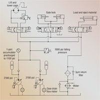
One of the hydraulic systems used on the hoist operates a conveyor motor and cylinder circuits as shown in the drawing. The system needs only one pump running, so the other serves as a standby pump. Each time the control system was started, it was set up to alternate the pumps so they would wear evenly and ensure that the stand-by pump did work before the last shutdown. If system pressure were to drop below 1000 psi, the stand-by pump would be started, and 3 sec later the first pump would be turned off, and an alarm would signal a problem with the first pump circuit.
During a run, the alarm sounded, the operating pump was shut down, and the stand-by pump was started. The maintenance supervisor issued a work order to change out the pump with a new one. This was accomplished with the system running because the three hydraulic lines to each pump were connected independent of each other and could by safely disconnected.
The pump case was filled with oil and would be started during the systems’s next down time, which happened two days later. Maintenance bled all the air from the pump. When pressure stabilized, and the pump quieted down, they ran several manual cycles without a problem. They then started the system, only to find that the electrical control circuit switched over to the stand-by pump before a complete auto cycle was finished.
What would you do next?
Robert J. Sheaf Jr., is the founder of Certified Fluid Consultants (CFC) and President of CFC-Solar Inc. CFC-Solar provides technical training, consulting, and field services to any industry using fluid power technology. Visit www.cfcindustrialtraining.com for more information.
|
Find the solution The correct answer will be printed in the next edition of “Troubleshooting Challenge.” |
|
Solution to April’s snow plow problem Turner Hydraulics felt that regardless of the possible problems in the valve assembly, the pump should compensate. The PAVC65 Parker pump is a little different from most load sensing, pressure compensated pumps because it does not have a case drain line. The case is part of the suction connection, and the drain line is actually a control drain. In addition to this difference, most pumps have the compensator and load sense controls assembled in a parallel circuit setup so the control with the lowest setting causes the pump to compensate. The Parker pump has its load sense differential spring area relieved by the maximum pressure compensator. They are confi gured in series, and changing the load sense differential spring increases or decreases the maximum compensator setting. It was discovered that the control drain and load sense connections were switched — causing the pump to respond like a fi xed-displacement pump without a relief. The two identical looking hoses were switched, and the pump began compensating. However, an additional problem was discovered. When the system was running in the neutral position, pressure dropped to about 125 psi. The system pressure should have gone to 2000 psi and compensated the pump. Further inspection found the directional valve outlet section was set up with a pipe plug isolating the pressure from the tank, making the valve a blocked-center type necessary for these types of pumps. They found the pipe plug threads were stripped and the plug was lodged in the tank cavity. This probably caused the “thump” noise when they fi rst started the system up. After this was corrected, the pump now compensates at the 2000 psi setting. |


