One way landfills have been dealing with containing more waste in limited space is by grinding municipal solid waste (MSW) to make it more dense — reducing volume by up to 35% over simple dumping, spreading, and compacting. MSW grinding creates smaller, more uniformly sized material. This creates less wear on landfill equipment that drives over the waste, and the smaller pieces of waste decompose faster.
Traditional MSW grinding involves pushing waste into a storage pit, picking it up in bunches, and depositing it onto a conveyor system for subsequent shredding. However, a newer technology uses a mobile tub grinder, which eliminates the expense of transporting waste to and from the shredder and setting up extensive conveyor systems. Diamond Z Mfg., Caldwell, Idaho, manufactures the SWG 1600, a machine that gives landfill operators much more flexibility in on-site MSW grinding.
Heavy-duty hydraulics
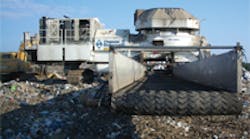
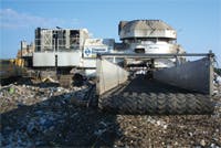
Traditional portable tub grinders are towed by a tractor rig to the grinding location. The 1600, however, has a track drive so it can navigate independently across a landfill. The 1600 is a traditional industrial tub grinder modified to process more than 300 tons of highly contaminated municipal landfill waste per hour.
Municipal waste typically contains stringy, wet, flexible materials, steel pipe, canisters, and similar components that can quickly clog screens in a conventional tub grinder. The 1600 uses a series of screening rods that can be retracted hydraulically to allow rapid cleaning.
Nearly every function on the machine has some hydraulic power behind its operation. The tub is driven by two hydraulic motors powering a sprocket and chain arrangement, the tracks are controlled through independent hydrostatic transmissions, and conveyors are each driven by independent hydraulic motors. The tub continuously agitates the material and carries new material over a hammer mill — a rotating cylinder featuring detachable hammers .
Grinding occurs in the mill area, where the hammer mill tips impact the material, breaking and tearing it into smaller pieces. The pulverized material is then pushed past the screening rods in a semi-circular arrangement to further reduce the product to a uniform size. These screening rods are hydraulically positioned by 5-in. bore, 96-in. stroke cylinders for size adjustment and cleaning when material wraps around or becomes lodged in between rods.
Processed material falls onto a 10-ft long primary discharge conveyor, located under the machine. A 66-in. wide belt travels at 500 ft/min and discharges into a secondary conveyor that is 50-ft long by 72-in. wide. The hydraulic drive motors produce belt speeds of up to 650 ft/min.
In control
The machine is fully remote-controlled through a multi-function touch pad in the cab of a excavator or loader. The remote control system manages all hydraulic functions from the cab of a excavator or loader. A feedback system built into the hydraulic controls senses the loads on the conveyor belts. If the pressure is too great on the motors driving the belts, the controller reduces power to the tub to stop processing material. This allows the belts to catch up and move the material off the conveyor and avoid a backup in the mill area.
Grinding functions are locked out while the travel mode is engaged. Once the grinder is properly situated, an operator feeds the grinder using a grapple attachment. The grinder automatically senses the rotating tub pressures if an overload occurs, and reverses the tub to relieve the system until the load is ground out or re-situated in the tub. The operator’s main function is to try to keep the tub loaded with unground material.
The tub motors are controlled by the engine speed sensing in the controller. If the engine is being overloaded, the tub motors pause and reverse at a preset time delay to allow the motor to regain speed. All grinder and track functions are capable of being controlled manually on the machine as well as by the multi-function remote transmitter.


