All of us have probably used the equation that relates the output flow of a pump to its displacement (volume per revolution) and the input shaft speed (rpm):
Q = (D × N) ÷ 60
and that calculates the input torque to a pump when operating at a certain output pressure:
T= (P × D) ÷ 2π.
These two ubiquitous relationships provide first estimates of pump or motor performance without having to labor tediously.
We might ask, for example, “How much flow can we expect from a pump with 3.3 in.3/rev of displacement when operating at 2400 rpm?” We do the calculation, get 132 in.3/sec (approximately 34.2 gpm), and adjust the final flow to about 85 or 90% of that value to allow for some volumetrelric inefficiency. So in a matter of seconds, we have a reasonable estimate of the expected pump output flow in some application. We can do a similar calculation with the torque equation, except we increase the torque value to account for mechanical and frictional losses in the power conversion process.
A simple model
The two equations taken together are a mathematical model of a positive- displacement hydraulic machine, and they work equally well for either a pump or a motor. It is commonly stated that the formulas produce “theoretical” values for flow and torque. I prefer a more descriptive word, “ideal.” That is, the formulas apply to a pump or motor which has no losses; it is 100% efficient in both volumetric and in mechanical respects.
Any practical machine, of course, has losses, and the model of the ideal machine produces erroneous values. But that does not render the model useless if our aim is merely a first estimate and if we apply some correction factors to account for the losses.
If we all use these equations — adjusting and tweaking their results with correction factors as our personal experiences and consciences might dictate — under whose authority have we accepted them in the first place? Never mind that we could derive them by applying the first principles of physics to the pumping mechanisms. It seems that knowledgeable experts in the field of fluid power technology should be passing judgment on these formulas to give them credence. In the process, they would give the limitations as to their credibility, suitability, and utility as predictors of pump and motor performance.
For this reason, I am proposing to the National Fluid Power Association’s Technical Board that applications- oriented, mathematical models of hydraulic pumps and motors be adopted and promulgated for manufacturers, users, and educators in the field of hydraulic technology. The proposal goes well beyond the idealized model described above. Instead, it uses the ideal pump and motor as a starting point, then proceeds to quantitatively define the performance of progressively more detailed, complex and, ostensibly, more accurate models.
A proposal for better models
The proposal to NFPA encompasses four different models that vary in degrees of complexity and precision relative to real-world machines. The first three models sacrifice some accuracy of results in order to produce a model (set of linear relationships) that is easily solved. The four models are:
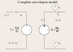
- Zero degree model has no losses and, therefore, is ideal. It is characterized completely by the two earlier equations.
- First degree model contains linearized, lumped parameter loss coefficients for internal leakage effects and friction. In this sense, linear means that leakage flow is directly proportional to pressure, and frictional torque loss is directly proportional to shaft speed.
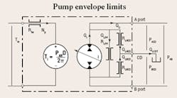
- Second degree model has linear loss coefficients, but also allows for internal leakage losses from port-toport and from either port to the case drain.
- Third degree model uses the same schematic representation as the second degree model, but the third degree model allows for several variations that are dictated by the specific nature of the pump or motor as well as the experience of the person doing the modeling. Notably, these effects can be incorporated:
- Frictional torque loss is a non-linear function of speed and varies with viscosity.
- Leakage is a non-linear function of pressure and viscosity.
- Leakage coefficients vary with shaft angular position.
- Displacement varies with shaft angular position and creates flow and torque pulsations.
- Any other non-linearities and/or power conversion aberrations that befit the experience of the person doing the modeling provide greater accuracy in the computed results.
Meaningful modeling
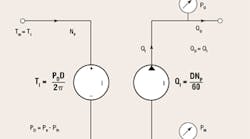
Modeling of physical components must convey specific meaning to readers draulic circuits. For example, the difference between the ideal machine and a practical machine must be expressed. This is done by putting the letter I inside the pump envelope, so that the reader of the schematic is not mislead as to the intent of the symbol. This can be seen in Figure 1.
We need another extension of the symbology to encompass the more mechanical parameters, for example, torque and speed. Those ideas are implied in Figure 1. The left half is the hydraulic analogous circuit for torque and rotational speed, with a bit of my own electronic education thrown into the mix. The rotation speed flows through the mechanical circuit and through the torque generator in Figure 1, with ± polarity to indicate that the pump’s pressure-induced torque is “fighting” the input speed. Therefore, the pump is trying to reduce the input speed from a prime mover, which is not shown.
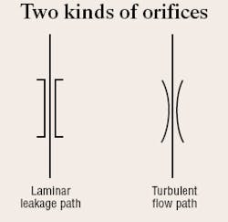
Other modeling features need to be conveyed as well. For example, flow can exist in either a laminar or turbulent mode. The laminar and turbulent modes have completely different models, therefore, it is necessary to convey which mode is at play. This reality has caused me to “invent” new schematic symbols, allowing me to make circuit diagrams for either flow mode. The flow path (orifice) symbols are shown in Figure 2.
Figure 3 contains the complete second degree pump model, showing its three different internal leakage paths, all of which are depicted as being laminar, and therefore, the leakage is linearly related to the differential pressure drop across each respectively. The newly proposed models will be covered in more detail in the coming issues of Motion Control. Specific features of the models, their uses in developing math models of entire circuits and systems and the methods for including dynamic effects will be explored and presented, as well. Special emphasis will be placed on their educational value.
Meanwhile, I encourage anyone interested in participating in the progress, review, modification, and improvement of these models to contact the National Fluid Power Association. Call Carrie Tatman-Schwartz at (414) 778-3347 or e-mail [email protected].
