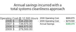
When all factors such as maintenance personnel hours, replacement parts, fluid consumed, and decrease in profitability are considered, it is easy to understand the substantial cost impact that occurs due to fluid that is poorly cared for. Identifying fluid contamination issues provides an excellent opportunity to lower operating costs and increase efficiency.
Applying a total systems cleanliness approach is necessary to maximize uptime, extend component life, extend fluid life, reduce maintenance resource demands, and reduce fluid disposal costs. For example, upgrading from cellulose to fiberglass filter elements, installing desiccant breathers, and installing off-line filtration can be quite effective in improving hydraulic fluid cleanliness.
A five step program
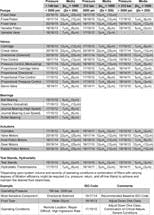
Step 1 — Set a target for fluid cleanliness for each system to be verified by periodic oil analysis with the results reported per ISO4406:1999. The ISO code results should be expressed in a three number code that uses the latest particle counter calibration, such as 4µ[c] /6µ[c] /14µ[c]. Target fluid cleanliness codes should be determined by the most sensitive component within the system. If the system is critical to safety or mill operation, then the target fluid cleanliness code should be one level lower than the suggested code for the most sensitive component on the system. The sidebar on page 30 details suggested ISO cleanliness codes for specific hydraulic system components.
Step 2 — Install desiccant breathers on all fluid reservoirs. Unprotected or under-protected reservoir vent ports can be one of the biggest sources of ingression. Although ingression can also come from unfiltered new fluid, filtering all new fluid will also help hold contaminant ingression in check.
Step 3 — Install high-efficiency fiberglass filter elements in all hydraulic systems to maximize fluid contamination removal.
Step 4 — Identify systems with insufficient filtration and add off-line filtration to continually filter the fluid during operation.
Step 5 — Develop maintenance procedures to monitor fluid cleanliness and filter element differential pressure (ΔP). Fluid sampling techniques and testing methods should be standardized to ensure consistent results of fluid analysis. Elements should be changed on a predictive maintenance schedule or when they reach a threshhold ΔP.
Measurable results
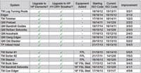
In one instance, a twin planer infeed hoist was one of the most contaminated hydraulic systems in the mill. The ISO fluid cleanliness code of the system fluid was 21/17/13 before implementing a total systems cleanliness approach. Two return filters, a pressure line filter, and a recirculation line filter were upgraded to Hy-Pro DFE filter elements with equivalent micron ratings. The reservoir’s breather was upgraded to a Hy-Dry desiccant breather to control particulate and water ingression. In less than 30 days the ISO cleanliness code of the fluid improved to 16/13/10.
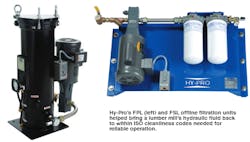
Furthermore, the mill’s twin sorter system was suffering from inadequate filtration. It was decided to add an FPL off-line filtration panel to achieve the target ISO cleanliness code. As with the twin planer infeed hoist, the twin sorter’s return line filter was upgraded to a Hy-Pro DFE rated filter element with equivalent micron rating, and its reservoir breather was upgraded to a Hy-Dry desiccant breather to control particulate and water ingression. In less than 30 days the ISO cleanliness code improved from 21/17/11 to 14/12/8.
When OEM specified filtration is either lacking in pressure, return, or servoactuator lines, or if housings are sized only to function with coarse media elements, effective results can be achieved by adding dedicated off-line filtration systems. Off-line systems can use high efficiency elements down to 1 µm to reduce contamination load on in-line filters to extend their life. Off-line filters can also be serviced without having to interrupt machine operation.
Adopt a Systems Approach to Hold Water at Bay
In addition to controlling particulate, a vacuum dehydrator can remove free, emulsified, and dissolved water from hydraulic and lube oil. Water in oil (which can be introduced by leaky heat exchangers or condensation) reduces lubricating properties, accelerates fluid degradation, and damages components. A Hy-Pro V1 portable vacuum dehydrator effectively keeps hydraulic and gearbox lube oils clean and dry throughout a plant.
Implementing the total system cleanliness approach to control contamination and care for fluids from arrival to disposal will ultimately result in more reliable plant operation and save money. Several steps to take when developing this system include:
• Evaluate and survey all hydraulic and lubrication systems.
• Establish an oil analysis program and schedule.
• Insist on specific fluid cleanliness levels for all new fluids.
• Establish a baseline and target fluid cleanliness for each system.
• Filter all new fluids upon arrival and during transfer.
• Seal all reservoirs and bulk tanks.
• Install high quality particulate and desiccant breathers.
• Enhance air and liquid filtration on existing systems wherever suitable.
• Use portable or permanent off-line filtration to enhance existing filtration.
• Improve bulk oil storage and handling during transfer.
• Keep water and moisture out of hydraulic systems and use approved techniques to remove water if it does get in.
• Make a commitment to fluid cleanliness.
Target ISO codes for fluid power components
When setting target ISO fluid cleanliness codes for hydraulic and lubrication systems, keep in mind that the objectives are to maximize equipment reliability and safety, minimize repair and replacement costs, extend useful fluid life, accommodate warranty requirements, and reduce or eliminate production down time. Once a target ISO cleanliness code is set, follow a progression of steps to achieve that target, monitor it, and maintain it to yield justifiable rewards for your efforts.
Set the target
The first step in identifying a target ISO code for a system is to identify the most sensitive component on an individual system, or the most sensitive component supplied by a central reservoir. If a central reservoir supplies several systems, the overall cleanliness must be maintained, or the most sensitive component must be protected by filtration that cleans the fluid before reaching that component.
Other considerations.
The table recommends conservative target ISO cleanliness codes based on several component manufacturers’ guidelines and extensive field studies for standard industrial operating conditions in systems using petroleum based fluids. If a non-petroleum based fluid is used (i.e. water glycol) the target ISO code should be set one value lower for each size (4µ[c] /6µ[c] /14µ[c]).
If any combination of the following conditions exists in the system, the target ISO code should also be set one value lower:
• if a component is critical to safety or overall system reliability,
• if frequent cold starts occur,
• when excessive shock or vibration occur, or
• other severe operation conditions.
Understanding ISO codes
The ISO cleanliness code (per ISO4406-1999) is used to quantify particulate contamination levels per milliliter of fluid at three sizes 4µ[c] /6µ[c] /14µ[c]. The ISO code is expressed in three numbers (example: 19/17/14). Each number represents a contaminant level code for the correlating particle size. The code includes all particles of the specified size and larger. It is important to note that each time a code increases the quantity range of particles is doubling and inversely as a code decreases by one the contaminant level is cut in half.
For more information, email [email protected], call (317) 849-3535, or visit www.hyprofiltration.com.
