Besides cleanliness rating and dirt-holding capacity, essential selection criteria for filters are, of course, pressure and flow. However, other factors are less obvious. Among the most overlooked of these are transient (instantaneous) flow and pressure. Potentially damaging consequences can result when a pump suddenly starts or stops or a valve shifts from fully open to fully closed.
One way to compensate for these inevitable flow and pressure transients is to incorporate an open or closed surge tank into the circuit. An open surge tank is used to accommodate excess flow and is similar to a hydropneumatic accumulator. However, the gas chamber is open to atmosphere. A closed surge tank is similar, but it has a throttling valve to regulate air flow to and from atmosphere. Closed surge tanks are used primarily to absorb and smooth out pressure surges.
Left unchecked, these pressure transients (spikes) travel like a wave from their source and through a hydraulic line until they dissipate. When these pressure waves encounter a rigid obstacle — such as a closed valve — they can even be retransmitted back into the system, toward the source. If this propagation and echo effect continues, system malfunctions can occur, and components exposed to these pressure and flow variations can undergo premature failure.
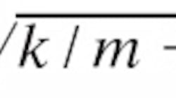
To further understand transient flow, parallels can be drawn between a spring mass system, such as in a car's suspension system, and transient flow. In a spring mass system, the natural frequency is:
where f is the frequency,
k is a spring constant, and
m is the mass.
When the amplitude (caused by the forcing frequency) is constant, the oscillations are steady vibrations. A hydraulic system can be viewed as having an infinite number of masses and springs and infinite modes of oscillation. In a closed system, oscillations can be caused by a boundary condition — as in a cyclic shifting of a valve or the starting and stopping of a pump — or oscillations can be self-excited.
When the forcing function is the cause of the oscillation, the frequency of the steady flow will be the same as the forcing function. If the oscillation is self-excited, its frequency will be at one of the system's natural frequencies. Three common types of forcing functions in hydraulic systems are
- periodic variations in pressure,
- periodic variations in flow, and
- variations in the relationship between pressure and flow.
Self-excited oscillations occur when a component in the system intensifies a small pressure or flow wave into a larger one. This causes an increase in system energy.
Avoiding transients
Many damaging transients can be avoided by using components that create minimal disturbances, such as soft-shift valves or a hydraulic overspeed control (HOC). HOCs often are used on newer rear-loading refuse trucks.
For hydraulic systems in which transients can't be avoided, many methods exist for controlling them. One of the most prevalent is a surge tank — a reservoir designed to accept momentary additional flow for dissipating the pressure wave within its volume.
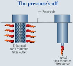
In-line hydraulic filters often are subjected to the transient flow due to their location in a return line. The filter housing can present a weakness in the system because it is subjected to the increased pressures, and the filter element may collapse under increased flow. Replacing the in-line filter housing with a properly-sized in-tank filter is a solution for the filter exposed to transients by allowing the reservoir to also serve as a surge tank, Figure 1.
Anatomy of a transient spike
Pressure and flow spikes can be viewed as transient waves that are quickly dissipated within a system. Many components can cause these spikes, including a large cylinder. The sudden shifting of a directional control valve or the cylinder reaching the end of its stroke will cause a spike in the system.
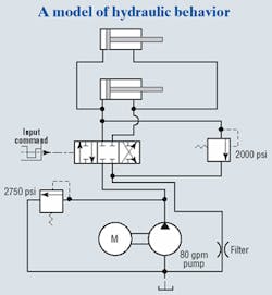
To illustrate, consider a common sweep circuit used on a trash collection truck. HyPneu simulation software from BarDyne Inc. (www.bardyne.com) simulates the circuit, Figure 2. The circuit contains two hydraulic cylinders, each with a 7-in. bore and 18-in. stroke. The circuit is driven by a fixed-displacement, 60-gpm pump and contains a return filter with a pressure drop of 16 psid at 80 gpm.
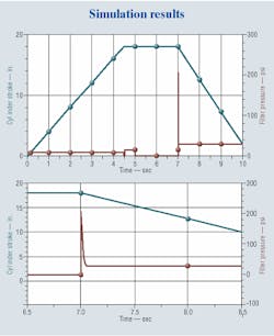
Step commands cause the directional valve to shift, thereby causing the cylinders to extend for first 5 sec, hold for 2 sec, then retract. The filter was modeled as an orifice with a flow coefficient of 20 gpm/psid. A higher flow coefficient indicates less resistance to flow. Naturally, then, flow coefficient will decrease as the filter collects dirt.
Many actions were taken to simplify this example, such as neglecting the hose and tubing in the circuit. The amount of hose, tubing, and the ratio between the two can amplify or suppress pressure and flow transient waves. Because hose is more compliant than metal tubing, hose tends to damp pressure transients. However, if disturbances occur at its natural frequency, the hose assembly can create transients. Also, operating parameters vary from truck to truck, so the simulation was conducted only to illustrate system spikes.
The results of the cylinder position and pressure upstream of the filter are shown in Figure 3. When the cylinder begins to retract, an instantaneous flow of 287.25 gpm occurs with an upstream pressure of 206 psi. The results of this simulation are instructive, but many other factors can change the results drastically.
Additional factors to consider
Other important factors include the operating temperature and viscosity grade of the fluid, ambient temperature, flow rates, tubing size, and cylinder size.
For example, ISO 46 oil, which is typically used in the packers, has a viscosity of 220 SUS at 100° F. At 30° F, however, the viscosity becomes 2400 SUS. The pressure drop across the filter element increases with the viscosity of the oil, so the flow coefficient decreases accordingly. However, the flow coefficient can be increased by placing the filter element within the reservoir.
It follows that a reduction in differential pressure at a given flow rate increases the flow coefficient, which, in turn, reduces the amount of energy that is trapped by the restriction. By reducing flow restrictions, the tank filter reduces the potential-failures due to transients.
In this system, the transients caused by a disturbance are quickly dissipated, but the potential problems they cause are not. The filter element and housing must be sized to accommodate these transients. Failure to do so can result in filter and system failure. For example, if the pressure seen by the filter housing is taken to be the pressure caused by the flow alone, it will be inadequately sized. Without taking into account the transient spikes, it might be feasible to use a filter with a fatigue strength of 150 psid. This undersized filter presents a potential failure, since pressures of greater than 200 are routinely seen. Furthermore, the filter element must be able to withstand a larger differential pressure caused by the increased flow.
Preventive measures
The hidden perils of a hydraulic system are easily avoided with diligent engineering, communication, and experience. But as systems continue to expand in complexity, chances of overlooking these adverse effects grow increasingly.
Using simulation software provides an invaluable insight into the idiosyncrasies of hydraulic systems that can be easily and graphically communicated. In addition, the potential dangers can be minimized by relocating critical components, such as using an in-tank filter.
With these tools of experience and advance simulation software, the challenges presented by dynamic systems can be addressed before they become a problem in the field. For more information, contact the author at [email protected] or visit www.parker.com/hydraulicfilter.


