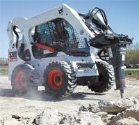
The S300 skid-steer loader from Bobcat Co., West Fargo, N. D., takes full advantage of the power and versatility of hydraulics. Its hydrostatic drive delivers 20.7 of flow for travel speeds to 6.9 mph, but a 2-speed option delivers 37.0 gpm for speeds to 12 mph. Also, the pump is driven through a belt assembly, enabling it to run at a higher speed than the engine. Operating the engine at a lower speed while still delivering maximum hydraulic power causes the engine to run quieter and increases its service life. The S300’s cadre of hydraulic cylinders provide lifting capacity to 3000 lb.
But that’s not all. The S300 has a variable-speed hydraulic fan drive that provides cooling closely matching that needed by the engine. The result is better fuel economy because the fan doesn’t run at higher speed than necessary, and the 81-hp EPA Tier 3 diesel engine runs more efficiently by running at a consistent temperature. The hydraulic fan drive is also up to 30% quieter than a conventional fan drive.
Considering all these impressive features, you might overlook one of the S300’s most valuable attributes: it can operate 70-different quick-change attachments and change from one attachment to another within seconds. This is done through Bobcat’s proprietary Bob-Tach system. The Bob-Tach system consists of a pair of mating flanges — one on the attachment and one on the S300’s lift arm. An integral part of this mating system is a pair of quick-acting couplings that transmit hydraulic power between the S300 and the attachment.
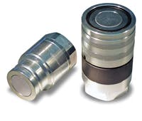
But these aren’t just any quick-acting couplings. They feature a flat-face design that doesn’t leak, even when connecting or disconnecting with pressure in the hydraulic lines. The flat faces of the coupling halves are easy to keep clean, which minimizes contaminant ingression into the hydraulic system.
Furthermore, the couplings are designed for minimal flow restriction. This feature reduces the pressure differential (ΔP) across the coupling, which maximizes hydraulic power delivered to the tool. Of course, the higher the flow and pressure available to the tool, the more productive it becomes.
Facing the facts
Quick-acting couplings have been in use for so long that most have become a commodity. However, dramatic differences in performance exist from one design to another. So specifying a coupling based primarily on price will result in a coupling that will likely exhibit one or more shortcomings. It may exhibit a high ΔP and restrict flow, it may cause substantial fluid spillage when connecting or disconnecting, it may wear out prematurely from pressure pulsations, and it may not allow making or breaking connections with fluid lines pressurized.
Matt Mulder, vice president at Faster Inc., Maumee, Ohio, says the flat-face design avoids most or all of these pitfalls. He also explains that Faster, and most other major quickacting coupling manufacturers, offer flat-face couplings that conform to ISO 16028 for worldwide dimensional interchangeability. However, he cautions that ISO 16028 only provides dimensional requirements for mating halves, so basic performance and wide variations in features and performance may exist from one manufacturer to another.
Mulder says that as is typical of flat-face hydraulic couplings, mating surfaces of Faster’s couplings are completely flat when disconnected, making it simple to wipe off any contaminants that may have accumulated. Beyond that, however, he explains that system designers should carefully consider internal design characteristics to determine if a coupling is best suited for a particular application.
Mulder points out some of the features of Faster’s line of flat-face couplings that designers should find important:
• No fluid spillage or air inclusion when lines are connected or disconnected. This feature keeps equipment clean and safe, and also avoids fluid spills that could be costly environmentally and economically.
• Internal component geometries are designed to maximize fluid flow with minimal ΔP.
• Sealing surfaces are rolled to ensure a tight sealing and low friction.
• Main seals feature a proprietary profile and are made of polyurethane to provide the best balance between sealing performance, fluid compatibility and wear resistance.
• Mating male and female surfaces are induction hardened and carbonitrided, respectively, to produce hard surfaces that are highly resistant to brinelling (surface pitting resulting from repeated high-pressure cycles).
Selection parameters
Mulder also outlines important points to consider when selecting his company’s flat-face quick-acting couplings:
Working pressure — Starting from the minimum burst pressure of the male half disconnected, female half disconnected, and when they are connected, apply a 1:4 safety factor corresponding to the most severe working condition.
Also consider that static and dynamic pressures may be quite different. A typical example of dynamic pressure occurs in earthmoving equipment, where sudden load variations on cylinders create sudden and sharp pressure peaks. This is the most critical situation when selecting a quickacting coupling. In fact, continually subjecting a coupling to repeated high pressure impulses could cause metal or brinnelling between mating parts. The characteristic pitting exhibited by brinnelling could cause fluid to seep from a disconnected coupling half.
Flow rate and ΔP — Hydraulic power transmission of the coupling depends directly its internal flow path. Like pressure, flow rate can also be static or dynamic. The greater the fluid velocity through the coupling, the greater the ΔP across it. So if a coupling exhibits even moderately high ΔP at low flow, the much higher ΔP at high flow could damage seals, even if flow surges are only brief. The result would be fluid leakage, and in extreme cases, the seal could even be extruded from the coupling. The lesson here is to ensure the coupling is sized large enough to accommodate maximum anticipated flow without excessive ΔP.
Fluid characteristics — Because the hydraulic fluid in the system will likely adhere to industry standards, selection does not present as great a challenge as pressure and flow considerations. However, the fluid must be chemically compatible with the coupling, especially its seal materials.
Temperature is also important, not only because it can affect seal performance, but if a fluid becomes more viscous at low temperature, it will create a higher ΔP as flow rate increases. Normal temperature of the hydraulic fluid in working conditions is roughly 50 °C. However, mobile equipment often begins work cycles with hydraulic fluid at temperatures below freezing. Therefore, couplings should be specified with seals that will remain effective at both highest and lowest anticipated temperatures of the application.
Also consider that if equipment is not maintained, high levels of contamination in the fluid could cause component malfunctions, including couplings.
Design features — Of course, selecting a coupling that meets all these parameters is a great start, but it doesn’t guarantee the optimum component for the application. The best selection matches the configuration to the application. To help reach a decision, consider these questions:
• Do one or both hydraulic lines need to block fluid flow when disconnected?
• Will couplings be connected or disconnected with one, both, or none of hydraulic lines pressurized? (Faster’s 4FFI couplings can be connected with both coupling halves under full pressure.)
• How much force can be applied to make or break the connections? (The 3FFI series can be connected with little effort even with the male or female half under full pressure.)
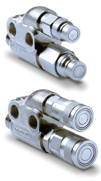
• If multiple hydraulic lines must be disconnected to remove a tool, would a manifold containing multiple couplings be practical?
Mauro Rambaldini, R&D Manager in Faster SpA, Rivolta d’Adda, Italy also contributed to this article. For more information on Faster’s flat-face couplings, visit www.faster.it.
