This file type includes high resolution graphics and schematics when applicable.
Leakage in hydraulic systems is a lot like the common cold. The achievements of technology are astounding, but we still haven't licked one of the most widespread nuisances. In general, the problem of leakage has become less prevalent and less severe. This leakage still is perplexing to many component manufacturers because leak-free designs of fittings — one of the main culprits — have been readily available for years. Seals — primarily rod seals on cylinders — pose a different challenge. This is because a thin film of clean lubricant is needed between the seal and rod surface. Without it, seals will undergo premature wear and, therefore, leak. But too thick a lubricant film also causes leakage, because the excess lubricant (hydraulic fluid) has to go somewhere.
If the products exist to reduce or eliminate the problem of leakage, then the solution lies with selecting the right product — and installing it correctly — for the specific application at hand. This may get the finished equipment out the door leak-free, but to hold leakage in check requires ongoing preventive measures. These often are not followed because most hydraulic systems continue to operate safely even when leaking. With electrical systems, on the other hand, components are maintained or replaced at the first sign of a potential problem. If an electrical cable is frayed where it enters a junction box, you can be sure the machine will be shut down and the problem corrected long before any sparks fly — which is a form of electrical leakage.
Because a leaking hydraulic system often poses no serious threat to safety or machine performance, leaks generally are viewed as a nuisance that can be fixed during the next scheduled shutdown and maintenance of the machine. Try doing that with an electromechanical drive that is shooting out a few sparks. If someone does try to correct a leak, the first action is usually to tighten a fitting, even though the fitting already may have been overtightened.
Leakage prevention, then, is two-fold. It involves not only selecting and installing the right component for the specific application, but maintaining the conditions that allow the component to continue performing without leaking. For optimum component performance, designers must be aware of the products available that achieve zero leakage for each specific application and how to install them. Users, on the other hand, must be aware of what they should do to keep the system operating without leaks.
Preventing leakage from components
Finding a component that promises leak-free performance poses no great challenge. All major component manufacturers offer products that meet SAE and ISO standards for reduced leakage. However, finding components that all deliver leak-free performance for an an entire machine becomes a tall order. This is because a fitting, hose, pump, valve, or cylinder may operate leak free for one application, but leak on another. Not surprisingly, then, most designers probably agree that achieving zero leakage throughout a machine involves a lot of trial and error.
Sometimes, one component may not leak on one machine, but an identical component may leak when used in a different area of the same machine. Case in point: a cylinder that actuates the first articulating member of an excavator's arm may not leak, but an identical cylinder (at the other end of the arm) that pivots the bucket may leak. The difference is, the cylinder pivoting the bucket may undergo severe pressure spikes from shock loading and impacts. Shock transmitted to the arm-actuating cylinder, on the other hand, may be much less severe due to damping within the machine framework and long lengths of hose.
Reducing the potential for leakage
In addition to using components designed for zero leakage, designers can also reduce the potential for leakage. This is done by minimizing the number of connections, all of which are potential leak points. One strategy for doing this is to integrate multiple components into one customized assembly. Years ago, custom-designed parts were practical only when quantities were in the thousands. But thanks to multi-spindle machining centers and computer-aided design and manufacturing, the break-even point for custom designed parts can be well below 200 pieces. (Scroll down to "Benefits of component integration" for details.)
Another practical approach is to specify hydraulic integrated circuits (HICs). HICs reduce the number of leak points by routing hydraulic fluid through a custom machined manifold block. Valves, switches, and other components are then mounted into cavities drilled into the block. HICs improve the design and performance in both mobile and industrial applications because they not only reduce leakage, but improve reliability and enhance troubleshooting. Still, the biggest reason for the popularity of HICs is cost. Even though the cost to design and machine a manifold is substantial, it generally is more than offset by the overall savings from having to use fewer parts. Dramatically quicker and easier installation, combined with greater reliability only add to the advantages of using HICs.
Maintaining zero leakage
The second strategy for achieving zero leakage is preventive measures that keep a system leak free. This involves more than fixing leaks as they occur and wiping off the fluid with a rag. Technicians need to be aware of the proper practices to follow to avoid situations that cause leakage.
To this end, many companies already have outlawed the use of pipe threads in new designs. And for equipment already using pipe threads, adapters are permanently attached to the component port to convert the connection to a standard leak-free configuration. Even so, the combined effects of pressure pulsations, vibration, and thermal cycles all can work a fitting loose over time.
Periodic inspection can go a long way toward preventing problems. For example, if hose cover wear is noticed where a hose rubs against a machine element, installing an abrasion-resistant sleeve can prolong the leak-free life of the hose. By the same token, if a hose occasionally gets snagged, installing a bend restrictor at the hose end may prevent it from fraying. When the hose assembly does wear out or begin to leak, replacing it with a version having an abrasion-resistant cover - or cut to a more appropriate length - can prevent future premature failure and leakage.
Piston rod seals can be the most vulnerable component in a system. Wipers and scrapers are intended to clean off a piston rod as it retracts into the cylinder. Still, even small amounts of abrasive material clinging to a piston rod can quickly cause the seal to leak. When this occurs, a bellows or boot can be installed to shield the rod from contaminants during extension and retraction.
Zero leakage at what cost?
Considering all these options available to hold leakage at bay, it should be clear that many occurrences of leakage can be prevented. The question becomes: is leakage a big enough problem to justify spending the time and money to prevent it? This is best directed to end users, because they are the ones who end up paying by tolerating leakage or preventing it. Equipment suppliers, then, can offer zero-leakage hydraulics to those who want it and are willing to pay for it.
Benefits of component integration
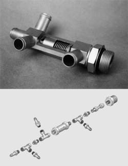
The component shown at right is a heat exchanger bypass valve for a cotton picker/sprayer. This integrated part protects seals in the equipment's hydrostatic transmission from damage caused by excessive pressure. Designed and manufactured by Fluid Line Products Inc., Willoughby, Ohio, it consists of an in-line relief valve set to open when exposed to 45-psig backpressure — well below the 60-psig rating of the seals.
Without the bypass, pressure in the HST's return line would likely exceed the maximum pressure rating of the seals when the machine is operated during cold weather. This is a common occurrence with mobile equipment because at low temperature, hydraulic oil has a high viscosity, which dramatically increases backpressure throughout the hydraulic system.
The bypass valve prevents intermittent leakage by keeping pressure applied to the seals below their maximum rating. Furthermore, it prevents permanent leakage by protecting the seals from excessive pressure. The bypass valve also prevents leakage by drastically reducing the number of mated joints (potential leak points) by nearly 70% from what would occur with standard components.
Darko Brozovic, project engineer manager at Fluid Line Products, explains that to duplicate the bypass valve using standard components, 11 fittings would have be be connected to a standard relief valve. Brozovic constructed the assembly drawing to illustrate how the bypass valve would be duplicated using standard, off-the-shelf components.
Although these components all are available readily available, the time and care to assemble them would add substantially to the overall cost of the bypass valve. Moreover, the potential for leakage would be more than three times as great, because the valve made from standard components requires 16 mated joints — as opposed to only five for the custom valve.
Not only must the components be assembled carefully to prevent leakage, but because the hose fittings must be connected in a specific orientation, leakage would likely occur if these fittings had to be repositioned for proper alignment during assembly. And if a leak did occur at one of the internal connections, the entire assembly would have to be removed because tightening one connection would loosen another. Consequently, any of the 11 mating connections could leak if even one is tightened or repositioned.
Additional benefits of using the custom bypass valve include a lighter, more compact design and a neater, cleaner appearance. In addition, because the component is custom designed, end users are much more likely to obtain a replacement part from the original equipment manufacturer. This not only supports a "genuine parts" strategy, but helps ensure that the machine will continue to operate more reliably. If a user made a replacement assembly from standard parts, the likelihood for leakage or breakage would be much greater — assuming the user could even connect and install the jury-rigged assembly.
Most designers, however, assume that a custom component, such as the bypass valve, is not cost effective unless ordered by the thousands. But John Hetzer, president of Fluid Line Products, Willoughby, Ohio, explains that this is not necessarily so. Hetzer says that the break-even point for most custom assemblies — even those far less complex than the bypass valve — falls around 175 pieces. Considering the many benefits of integrating multiple components into a custom design, leakage prevention is only a drop in the bucket.
Progress in leakage reduction*
Leakage of hydraulic systems is still a big reason why many designers shy away from hydraulics when they need to specify a power transmission system. Electromechanical systems usually win out, even though a hydraulic systems would clearly provide a more practical solution. The question is, how is the battle against leakage going?
As in most of industry, advances in technology trickle down after finding success in aerospace equipment. Leakage control is no exception. We can look to the aerospace industry to gage the progress made in approaching a goal of zero-leak hydraulics. Detailed documentation of aircraft maintenance records is the primary reason why this information is available.
In the 1950s, a hydraulic leak occurred roughly once every 17.5 hours of flight time in military aircraft. In the 60s, the occurrence was reduced to once every 23.8 hours. The latest records, for 1980 through 1996, show a reduction in leakage frequency to once every 50 hr of flight. What's important about this figure is that leakage frequency was cut in half, even though system pressure increased by 1/3 — from 3,000 psig to 4,000. The goal for the next 10 years calls for another reduction in leaks by one half, even though system pressures are expected to increase to 5,000 or 6,000 psi.
To what can this success be attributed? There is no single answer. Advancements in sealing and fitting technology probably account for the evolutionary improvements — especially through 1980. Moreover, improvements to computers, software, instrumentation, and information analysis allowed testing to provide more detailed and meaningful results. For example, tests on the B-1 bomber revealed that portions of two nearly identical high-pressure lines happened to have a natural frequency equal to the predominant frequency of the pump when the aircraft was at cruising speed. Redesigning the lines virtually eliminated the leaks.
But perhaps just as important as these was a change in how tests are conducted. Formerly, components were qualified if they passed specific tests. One problem with this procedure was that there was no way of assessing the weaker of two competing parts that both passed qualification tests. Instead, parts now are tested until failure. This reveals the merits of one part over a weaker competing part, even though both would pass standard tests conducted for a finite period of time or number of cycles. Second, tests were designed to evaluate the system, not just the components. Doing so allows evaluating the interaction of components to each other and within the system. As a result, in a span of less than two years, the occurrence of hydraulic leaks was reduced from once every four hours to once every 40 hours in design modifications to the B-1 bomber.
*This information was excerpted from material presented at the 1999 symposium of SAE's A-6 Committee: Aerospace Fluid Power and Control Technologies.
This file type includes high resolution graphics and schematics when applicable.


