This file type includes high resolution graphics and schematics when applicable.
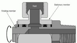
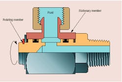
Even the best hose assemblies can fail prematurely if adequate allowance for movement of machine elements is not provided. One effective solution uses swivel fittings to allow hoses to pivot, which prevents or reduces stress from bending, twisting, stretching, and kinking. These simple singleplane swivel fittings, Figure 1, more than pay for themselves by extending hose life and reducing maintenance and downtime.
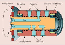
That describes one end of the swivel spectrum. At the other end are swivel joints that transmit fluid for multiple circuit lines through a single manifold that rotates continuously, i.e., a rotating manifold, Figure 2. In general, fluid enters one or more ports in the stationary half of the manifold and exits through a port on the other half, which rotates with the machine. A rotary seal between the two halves contains the pressurized fluid, yet allows relative rotation between the halves. For simplicity of discussion, the term swivel joint will be used here as an all-inclusive term to describe swivel fittings and rotating manifolds.
The rotary seal is probably the most critical part of the device, whether a swivel fitting or rotary manifold. This is because the seal between the rotating and stationary halves must be tight enough to prevent leakage of pressurized fluid, while introducing as little torque drag as possible. Torque drag is a measure of the swivel joint's resistance to rotation. These seals vary in complexity depending on the application. For simple swivel fittings undergoing less than 360° of rotation, the seal may be little more than two machined surfaces forced together. Rotating manifolds may require ball bearings and springloaded seals with auxiliary loading by fluid pressure. If the seal is not pressure balanced (fluid pressure acting on opposite sides of the seal), torque drag may increase with fluid pressure.
As with any custom-engineered product, manufacturers can supply a swivel joint to meet virtually any specification. However, a variety of standard swivels is available to keep costs reasonable.
Configurations
Most swivel fittings are standard catalog items considered specialty fittings. However, depending on their complexity and the standard product line of the manufacturer, rotating manifolds often are engineered items that must be special ordered, especially if more than four independent flow paths are required. Standard configurations of swivel joints include straightthrough (where flow paths are coaxial) and right-angle (where outlet ports are perpendicular to inlet ports). A less common design is the offset configuration, which is essentially a straight-through design with a 90° elbow integral to each end.
Available space and fluid line routing generally determine which configuration should be used. Keep in mind that axial length of a rotating manifold increases with the number of independent flow paths. In some applications, directional control valves can be mounted on the rotating end of the machine to allow routing only two common flow paths (pressure and return) through the rotating manifold. In this manner, all valves connect to the common flow paths through a conventional manifold or line fittings.
Other considerations include through holes and integral valving. A hole through the center of the rotating manifold may be necessary as access for electrical lines, a shaft, or other machine elements that must be routed from the stationary member to the rotating one. In some instances, valving is built into the rotating manifold to allow or block fluid flow as the rotating member advances through a revolution. Internal passageways open and close as the manifold turns, allowing fluid to flow only when the rotating member is in certain positions — a setup that operates much like a mechanical cam. As with a cam, this arrangement is not as easy to reconfigure as using electrically actuated valves. However, it can be very practical for applications that have a repetitive, fixed operation— such as an indexing table.
Type of motion
Just as swivel joints and rotating manifolds should exhibit minimal friction to allow free rotation, hoses and piping should transmit as little external load to the swivel joint or manifold as possible unless the swivel joint is designed with adequate bearings to support external loads. Otherwise, seals can wear prematurely and cause leakage. In extreme cases, the rotating joint itself may fracture.
Keep in mind that just the weight of components — hoses, tubing, and fittings — may be substantial enough to transmit an external load to the swivel. For example, the weight of a 10-ft section of spiral-wound hose may be overlooked, but can impose a substantial side load or bending moment on a swivel joint — especially if the hose is filled with hydraulic fluid.
Size and mounting
Obviously, the swivel joint must have ports of the correct size and geometry to accommodate hose and/or tubing assemblies mating to it. Ensure that enough room is available on the equipment structure to accommodate the swivel joint. For swivel fittings — as with any fitting — the higher the flow rating, the larger the ID and external envelope of the fitting. For rotating manifolds, enough clearance must be provided between ports to allow threading and unthreading hose-and tube-end fittings to the manifold. Also keep in mind the physical size of the rotating manifold. The more fluid lines routed through the manifold, the longer its axial length. The greater the flow through the manifold, the larger its required OD.
A means must exist to either mount the swivel to the structure or to mount the connecting hose and/or tubing to the structure adjacent to the swivel joint. This practice helps prevent misalignment from long runs of unsupported hose or tubing. Misalignment can transmit side loads to the swivel, causing the detrimental effects outlined above. Side loading can also be introduced by forcing misaligned rigid tubing into position for mounting. The assembly may fit together, but life and performance of the swivel joint may suffer.
Selection considerations
When selecting swivel joints, not adhering to manufacturers' specifications can result in leakage, premature failure of the joint, premature failure of hose, or all of these conditions. Exceeding manufacturers' published pressure ratings can cause fluid leakage by pushing fluid past the joint's rotary seals.
Excessive pressure can also increase friction, leading to premature wear and higher torque drag. Excessive torque drag can damage hoses because motion is transmitted to the hose instead of the swivel.
Also ensure that the swivel joint is compatible with the application environment — the chemical composition of the fluid being used, its temperature, and the external environment. Swivel joints are readily available in steel, stainless steel, brass, and other popular materials to match the chemistry and temperature of the fluid and surroundings. Perhaps more importantly, a variety of seal materials is available to accommodate virtually any hydraulic fluid at virtually any temperature.
Whenever possible, mount the swivel joint where it will have minimal exposure to abrasive or corrosive particles. In some applications, an elastomeric boot, bellows, or cover may be necessary to help isolate the seal area of the swivel joint from an extremely dirty environment.


