First year students in basic hydraulics are taught that cylinders will retract faster than they extend. There is truth to that assertion, but it has significant limitations, and they can lead to misunderstanding, if not the occasional surprise. The discussion that follows assumes that the cylinders in question are of the single rod-end variety, also called asymmetrical cylinders. These are, by far the most common type, all hydraulic applications considered.
In a system using a positive displacement pump, with all the pump flow directed to single cylinder, then indeed, when that pump flow is directed into the cap end of the cylinder, extension will be slower than if that same amount of flow was directed into the rod end. This is a pump limited, or pump controlled cylinder application. An important exception is in applications that use pressure compensated pumps and valves to control actuator flow, but there are other limitations as well.
The role of valves
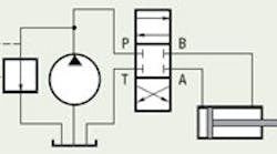
Figure 1, a basic and conventionally configured pump limited system, shows a fixed-displacement pump, directional control valve, cylinder, and pressure limiting relief valve. If the valve is fully shifted, first to extend, and then to retract, clearly, retraction will be done at higher speed than extension. However, the conclusion requires certain limitations to exist.
For example, if the valve lands are so restrictive as to raise the pump pressure to the level where the relief valve opens, a flow division diverts some pump output through the relief valve, leaving less for the cylinder. This will result in reduced cylinder speed in whichever direction because the relief valve is active.
There are other limitations. For example, if the closed center valve of Figure 1 is replaced with an open center type, there is a built-in flow division throughout a portion of valve shift away from center. This division is not obvious in the standard ISO directional valve symbology because it does not convey the concept of metering and proportioning of flow.
But whatever the ISO symbology limitations, there is indeed a flow division, and both the pump pressure and the cylinder speed are a function of the amount of valve shift, the direction of valve shift, the cylinder hydraulic areas, and the load on the cylinder. The only assurance of higher retraction speed is if the retraction and extension are compared with full valve shift, and low enough load and low enough valve pressure drop that the relief valve is not active. Under any other conditions, no generalized statement can be made about the extension versus retraction speed.
The function of many directional control valves is to meter flow, and thus control cylinder speed. It seems, then, that violation of the higher-retraction- speed-rule is really an exception. Only with discrete on-off valves can one make any generalizations.
Variable parameters
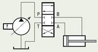
Now, what of that case where a pressure compensated pump is used in conjunction with a valve, and the valve is being used to control the cylinder speed? This system is sketched in basic form in Figure 2. When the valve is fully shifted to extend the cylinder, the extension speed will be greater than when the valve is fully shifted to retract the cylinder. But there are some qualifications to this assertion as well:
First, the pump must be of sufficient flow capacity that no matter how much or in which direction the valve is shifted, the pressure compensator is always active. That is, the pump displacement must always be less than full stroke. This is a desired goal when designing systems that use either servo or proportional valves for motion control.
Second, the valve lands must have the same amount of flow area when shifted fully in either direction. This is a situation where the valve coefficients (KVs) are the same for both directions of shift. Such a valve is referred to as a symmetrical valve.
Third, the load must be the same in both directions, which is a condition that requires even more qualification, but the technical details will have to wait for another installment of Motion Control. Suffice it to say that the simplest situation is when the cylinder load is zero or very low in both directions. These systems are designed so that the valve is limiting flow over its entire range of spool shift. Therefore, the pump’s compensator must be active and limiting the pressure. If the compensator goes inactive, it means that the pump is undersized — an undesirable situation, especially in servo applications.
Bridging the analysis
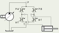
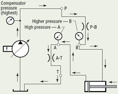
Why this is true can be seen by first recognizing that a 4-way directional control valve can be redrawn in analytical schematic form as a bridge circuit, shown in Figure 3. It is a relatively simple experiment to set up such a circuit and test it. It normally does not take any instruments to see the slower retraction, and it is always revealing in a student lab.
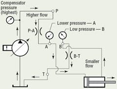
There are four individual lands in the 4-way valve, all controlled by the spool mo v eme n t . Wi t h spool shift to extend, lands P-A and B-T open while lands P-B and A-T go into overlap, or, nominally, they are closed. Figure 4 shows the active flow paths for extension. When the spool is shifted to retract, Figure 5, P-B and A-T are open while P-A and B-T are in overlap. The small arrows outside the circuit lines trace the flow directions.
The reason for the slower retraction speed can be seen by comparing the A-port and B-port pressures for the extend versus retract situations. In extension, the lower flow of the rod end is pushed back to tank through the valve’s B-T land. With a low return flow, a low pressure is all that is needed. The motivation force for the rod end flow derives from the cap end pressure, which is lower than the rod end pressure because of the cylinder area ratio. Recall that we are assuming that there is no load on the cylinder. With a low cap end pressure, and the pump operating at compensator pressure (recall that the system is assumed to have been sized so the compensator is always active), there is a relatively high pressure drop across the P-A land, providing a large cap end flow. The result is high extension speed.
On the other hand, for retraction, Figure 5, the large cap end flow has to be forced back through the A-T land, requiring a relatively high pressure on the cap end. Again, the area ratio comes into play, and the propelling rod end pressure must be higher still. The result is a pressure drop across the P-B land that is insufficient to propel the cylinder at a speed as high as that gained while extending. This reality can be seen by simple lab experiment, as well as by calculation. The speeds are fully predictable, but the calculations will not be covered now.
So what is the correct rule for extension versus retraction speed of an asymmetrical cylinder? Just change one word in the opening assertion: cylinders sometimes retract faster than they extend. Knowing the conditions is key to gaining a command of asymmetrical cylinder peculiarities.
