Every city wants to have an icon — a symbol that most people immediately recognize and identify with the city. The Eiffel Tower (Paris), the Statue of Liberty (New York), the letters in the Hollywood Sign (Los angeles), and the Gateway Arch (St. Louis) are examples. Many people in Milwaukee believe that the Burke Brise Soleil, atop the new Quadracci Pavilion at the Milwaukee Art Museum can play the icon role for them. (The eye-catching Soleil also provides a practical function — aiding climate control inside the new structure.) This graceful, movable sunshade consists of a pair of wing-like structures, each made up of 36 steel ribs ranging in length from 24 to 105 ft.
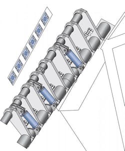
The ribs are mounted on two rotating steel shafts, in turn connected to the pavilion's spine. To open and close the sunshade, 22 hydraulic cylinders (11 on each side) stroke simultaneously to operate cranks attached to the shafts. The cranks swing a 90° arc to open the wings in 3-12 minutes.
Hadady Hydraulics Inc., Lansing, Ill., custom-built the hydraulic cylinders. These actuators — rated for 5000-psi service — have 230-mm bores and 125-mm rods. They stroke 26-12 in. Their design includes a forged alloy piston rod with a special rod-eye hinge (for installation ease). They have special sealing and guide elements for the rod and piston. Non-lubricated bearings in the rear pivot mount and the rod eye work on stainless steel pins throughout the operating cycle.
All under control
Although the actuator arrangement is relatively straightforward, the electronic system — designed, built, and installed by the Oilgear Co. — that controls and synchronizes the hydraulics has to be ready to deal quickly with a variety of external factors. In particular, the huge surface area of the sunshade can be subjected to very high forces when wind speed picks up. The shade also is exposed to other weather events. When necessary to protect the sunshade and the building structure that supports it, the control must be able to operate even if hydraulic or electrical power is lost. To meet these safety requirements, the control system interfaces with a number of sensors and includes appropriate redundancies.
For example, Oilgear engineers equipped the Art Museum building with two separate ultrasonic wind sensors to monitor velocity and direction. (Duplicate sensors are installed to help ensure that all wind gusts will be detected.) If wind speed exceeds 23 mph for three seconds or longer, the control system automatically closes the wings. Similarly, a lightning sensor is installed to predict imminent lightning strikes. Again, the control automatically closes the wings if it detects lightning.
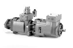
The power unit consists of two identical pump sets. Each 30-hp motor drives a tandem axial-piston pump. The pumps are Oilgear's Model PVWH11 with servo control. One pump of each tandem set powers the north wing, the other powers the south wing. This circuit can move both wings even if one motor-pump group is out of service — although at half the normal speed.
The control system monitors system pressure during operation and will automatically destroke the pumps to prevent overloading the electric motors. The control system stops the wings if pressure levels exceed a programmed limit. In addition, the control system monitors the strokes of all four main pumps. If any pump stroke does not match its command, the respective motor is stopped to prevent uncontrolled motion. The control also monitors hydraulic oil temperature and will not open the wings if it is too hot or too cold. (The operating temperature range is 0° to 140° F.)
The rotating shafts are equipped with two rotary-position transducers, one on each end of the shaft. These encoders detect any shaft twisting, which might occur if there is mechanical binding or excessive wind force. To prevent uneven loading on the building, the control also monitors the positions of both wings and maintains them within 0.1° of each other.
Each cylinder receives fluid through a flow-control manifold. The manifolds are fitted with orifices to control the extension and retraction speeds of the cylinders. This limits the speed at which the wings can fall if a pipe or hose bursts. The hydraulic system also is equipped with manually operated bleed-down valves. These valves serve as a back-up means of lowering the wings. And each wing has a limit switch to verify full-closed position.
Two backup systems
A diesel-powered back-up generator can operate the wings if electrical power to the building is lost. The hydraulic system is equipped with electrically operated hold-up valves so that electrical power is required to hold up the wings. If electrical power is lost, the hold-up valves de-energize and the wings close under their own weight at controlled speed.
As a final safety arrangement — to back up the back-up generator — a 16-hp, propane-fueled engine driving an Oilgear axial-piston pump provides hydraulic power to move the wings even if no electrical power is available.
Application engineer Tim Becker at the Oilgear Co., Milwaukee, provided details about this application.


