Compressed air is clean, readily available, and easy-to-use, but it can also be the most expensive form of energy to use in your facility. Unregulated or improper pressure settings can increase compressed air demand, which results in more energy consumption. A rule of thumb states that every 2-psig increase in operating pressure adds an additional 1% to compression energy cost. Point-of-use filters and regulators are needed to ensure that every tool or process is receiving a clean supply of compressed air at the proper pressure to provide peak performance.
Airline Filters
Reliability is one of the biggest reasons to use compressed air, and proper filtration is the key to maximizing reliability and longevity. Compressed air can carry condensed water, oil carryover from compressors, solid impurities generated within the pipelines, and wear particles from actuators. These contaminants can cause problems and should be removed by installing suitable filters.
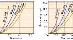
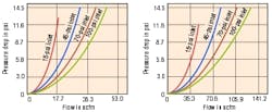
Contaminant-particle size is measured in micrometers (µm) — onemillionth of a meter or 0.000039 of an inch. Filters are rated based on the nominal minimum particle size the element can trap and retain. Although filters rated at 40 to 60 µm are adequate for protecting most industrial applications, many point-of-use filters are rated at 5 µm. Note that finer ratings increase the pressure drop through the filter, which equates to higher energy cost to compress the air. In addition, finer filters can clog quicker, increasing pressure drop. To avoid this, many manufacturers increase the element's surface area, which increases the element's flow versus pressure drop and life. Many filter manufacturers will define the expected pressure loss and dirt holding capacity using curves related to pressure and flow. Therefore, particleremoval filters should be selected based on acceptable pressure drop and pipe-connection size. A typical initial pressure drop through such filters is between 1 and 5 psig. A filter with larger body size will produce less initial pressure loss and provide longer operating life than a smaller size filter with the same removal ratings. The charts in Figure 1 compare pressure drop through several particulate filters that have identical 5-µm removal capacity.
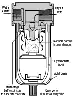
Point-of-use filters also remove condensed water from the airline typically via centrifugal action, Figure 2. The efficiency of water removal depends on incoming air velocity. If airflow is too low, the centrifugal action will be inadequate for proper water removal. If flows are too high, the pressure drop can be excessive. Take care to properly size the filters and pipe. If the filter is intended to remove-moisture, an integral automatic-float-type drain should be provided to periodically remove accumulated liquids from the filter bowl. Generally, such filters have transparent polycarbonate bowls, which allow visual inspection of the sump level. Numerous chemicals can attack this plastic material and it only performs well at pressures below 150 psig and temperatures between 40° and 120° F. A metal bowl may be necessary when the filter could be subjected to conditions outside those limits, as well as when synthetic compressor lubricants, which often contain chemicals that are harmful to polycarbonate, are present.
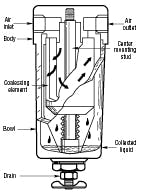
Most oil entrained in a compressed air stream, as well as some of the condensed water, will be in the form of mists or aerosols that can pass through the openings in standard airline filters. Air for instruments, spray painting, and bulk-material conveying frequently requires the removal of such droplets. Coalescing-type filters, Figure 3, accomplish this job. Aerosol carryover through such filters is commonly stated as parts per million (ppm) of oil versus air by weight and will range from 1 to as little as 0.01 ppm.
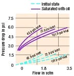
Coalescing filters are often rated to remove aerosols that are substantially smaller than the nominal size of the tiniest solid particle that could be captured. Some models offer dual-stage filtration. The first stage removes solid particulates to protect the coalescing element in the second stage. Because all coalescing filters create a greater restriction to airflow, pressure losses will be higher than those of conventional compressed air filters. Coalescing filters have an initial ( or dry) pressure drop and a working (or saturated) pressure drop, both based on pressure and flow rate. The effective removal efficiency of such filters depends greatly on the air velocity passing through the filter assembly. Choose a coalescing filter based on acceptable oil carryover, expected airflow rate, and pipe-connection size. A coalescing filter rated at 0.1 ppm will typically have a clean, wetted pressure drop between 2 and 5 psig, while a high-efficiency filter rated at 0.01 ppm can cause as much as a 10 psig drop once it becomes wetted or fully saturated during service, Figure 4.
Pressure regulators
Once a minimum suitable operating pressure has been determined for any compressed air application, the air must be supplied at a constant pressure regardless of system pressure or flow variations. Therefore, it's critical to install the proper regulator or pressure-reducing valve in the airline. Air regulators are special valves that reduce supply pressure to the level required for efficient operation of downstream pneumatic equipment. It's always a good idea to install a filter upstream from the regulator to protect it from dirt and water in the system.
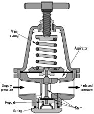
Most pressure control regulators feature either a piston or diaphragm control construction and a balanced poppet. A typical pressure regulator, Figure 5, functions when the adjusting knob is turned clockwise, applying a load to a control spring. This load causes the piston/diaphragm and the valve poppet assembly to move downward, allowing flow across the seat area created between the poppet assembly and the seat. Pressure in the downstream line is sensed below the piston/diaphragm and offsets the load of spring. As downstream pressure rises, poppet assembly and control piston move upward until the area is closed and the load of the spring and pressure under the piston/diaphragm are in balance. A reduced outlet pressure has now been obtained, depending on spring load. Creating a demand downstream, such as opening a valve, results in a reduced pressure under the piston/diaphragm. The load of control spring now causes the poppet assembly to move downward, opening the seat area and allowing air to flow to meet the downstream demand. The flow of downstream air is metered by the amount of opening.
Regulator construction varies based on size and performance requirements. Mini regulators will typically be unbalanced poppet style with a combination flow and diaphragm chamber. In larger, more expensive regulators, construction features a balanced poppet and a separate diaphragm chamber with an aspiration opening exposed to the output pressure. Separating the diaphragm chamber from the outlet pressure minimizes the effects flow can have on a regulator's ability to sense and respond to outlet pressure, thus improving performance. A balanced poppet further improves a regulator's ability to control set pressures by reducing the effects of upstream pressure variations. This style regulator has minimal droop as system conditions vary.
Figure 6 compares how performance can vary between small and large diaphragm units, with the larger diaphragm units having improved response and sensitivity. As discharge flow through the regulator is increased over its entire range, output pressure droops, Figure 7. It's important to set the regulators desired output pressure under normal flow conditions.
Precision regulators use single or double diaphragm chambers and reduced poppet areas to improve performance. Precision regulators will typically also have a constant relief bleed, which improves a regulator's accuracy and ability to relieve excess pressure. To select the best type of regulator for a specific application, you must know the supply pressure, downstream or set pressure, flow required, adjustment type, and accuracy.
Adjustment methods usually normally offered are either a nonrising knob style or a T handle. Non-rising knob style regulators are the most common, but T handles are frequently used in rugged and oily environments. Many regulators will be available with multiple spring (adjustment) ranges. Try to choose a regulator with a spring range twice as high as the desired set point. For example, use a 0 to 125 psi spring range for a 60 psi desired set point. A typical industrial grade regulator will have an accuracy of 2 to 4 psi when the proper flow and spring selections are made. Applications with a higher accuracy need a precision regulator that lets users set and hold a pressure within 0.05 to 0.5 psi.
Modular or Combination Units
Manufacturers frequently pre-assemble filters, regulators, and lubricators to form combination units (FRLs). They're packaged together as common body sizes with common connection port sizes. Modular connections also ease conversion between metric and inch port types. Interconnections may be via threaded nipples or modular face connectors. Modular connectors facilitate component removal for servicing or cleaning. In addition, some manufacturers combine filters and regulators in stacked assemblies where the filter head becomes the regulator body. The components share common inlet and outlet connections, which makes the assembly very compact.
Such packaged units, whether FR only or FRL, are practical choices for most industrial applications. The selection criteria are the same as with any of the individual components, except that the combined pressure and flow performance becomes the only consideration. Note that when critical requirements dictate the use of specialty filters or precision regulators, the assembly probably must be made up of individual selections and connected with pipe nipples.
There are three common styles when assembling air preparation units. Pipe nippled units use threaded connectors to join individual units together. This style is the most cost-effective, but lacks flexibility. Semi-modular styles use a bolt and O-ring to join units. They are more attractive in appearance and have a smaller overall width than pipe nippled units. They have greater flexibility in adding components than piped units, but cannot be as easily serviced as modular units. This style is typically more expensive than pipe nippled units, but it's still very cost effective.
Modular styles use a special connector to assemble individual units. The modular connectors replace the pipe nipple and bolt of the previous styles and give much greater flexibility in adding and removing components from an assembly. Modular connectors also make the conversion between inch and metric porting much easier.
Fig. 1. Pressure drop plotted against flow for airline filters with 1/4-in. ports, left, and 1/2-in. ports, right.
Fig. 2. Cutaway view of air flow through representative compresse dair point-of-use filter.
Fig. 3. Cutaway view of air flow through typical coalescing compressed-air filter.
Fig. 4. Plots illustrate how pressure drop across coalescing filter increases after element is wetted.
Fig. 5. Cross-sectional view of typical regulator.
Fig. 6. Plots of secondary pressure against supply pressure for regulators with small and large diaphragms illustrate how pressure droop varies as supply pressure increases.
For more information, visit www.parker.com/pneumatics.
