Hydropneumatic accumulators are widely used in hydraulic systems because they provide auxiliary power during peak periods. This lets designers select smaller pumps, motors, and reservoirs in the main system.
Accumulators are also widely used in leakage compensation and holding applications and, in off-road equipment, for braking, ride control, steering, dead-engine pilot, and tensioning systems.
Beyond their basic use, accumulators are finding their way into new applications due to an ability to save energy, reduce initial and operating costs, handle high payloads, and prolong equipment life.
With today’s high fuel costs, a promising new application with significant payoffs and benefits uses accumulators as rechargeable hydraulic batteries. These recover and store previously lost energy and use it to supplement pump flow in mobile and stationary equipment.
Energy recovery
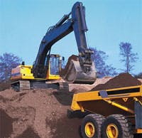
Excavators, for instance, are prime candidates for energy-recovery systems. The machine’s massive arms, when lowered, generate a great deal of force on the rod end of the lift cylinders. In turn, this exerts huge forces on the fluid and blind end of the cylinders. Fluid forced from the cylinders — at several hundred psi, in most instances — throttles through valves and returns to the reservoir. The result: potential energy in the elevated lift is lost as heat when the arm lowers.
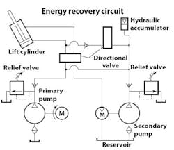
Energy recovery systems, in contrast, use the high-pressure fluid being expelled from the cylinder to drive a hydraulic motor. The motor, in turn, drives a hydraulic pump that charges an accumulator. Energy stored in a piston or bladder accumulator can subsequently be harnessed to supplement pump flow and help lift the excavator arms and load on the next work cycle.
For example, if lowering the excavator arms displaces 7 gal of fluid at 1000 psi, the hydraulic motor can drive a hydraulic pump and develop 2175 psi or more. This high-pressure fluid can then be stored in an accumulator for use in the next lift cycle.
Such energy-recovery systems make it possible to reduce pump size by 25%, with resulting fuel cost savings as high as 30 to 35%.
Excavators with energy recovery features generally command about a 15% premium over the cost of standard machines, depending on fuel or electricity prices. In addition to excavators, energy recovery generally produces the best payback on loading and trenching machines. Forestry excavators with accumulators, for example, have a fuel-cost savings of about 25 to 30% because they can use smaller diesel engines. Typical machines used in construction applications yield a 10% savings.
In addition, most loading cycles have about 20 sec when full pump flow is not used. As a result, the primary pump operates in a partially compensated mode and draws less power. Pump flow during this dwell time can also charge an accumulator. Then, when the hydraulic system requires full flow, the accumulator can supplement flow from the pump. Here, designers taking advantage of this concept can significantly reduce the size of the primary pump.
A typical accumulator system stores 8½ gal of fluid at pressures between 1150 and 2175 psi. Fluid discharge from the accumulator takes about 5 sec, or a flow rate of 102 gpm. Combining flow from the accumulator’s 8½-gal fluid volume with the output of an 80-gpm pump generates flow rates of 108.7 gpm during the 5-sec time span. The instantaneous flow of fluid stored in the accumulator combined with that of the primary pump results in a faster, more-responsive system.
Generally, excavators use a 50-gal piston accumulator supplemented by 50-gal gas bottles — pressurized vessels that increase capacity — for a total gas capacity of 100 gal. Smaller machines use about 30 gal of gas capacity. Some manufacturers of smaller machines gang five 6-gal piston accumulators. Others OEMs prefer six 5-gal bladder combination units.
Using gas bottles in conjunction with an accumulator can significantly reduce costs as well as save space. Gas bottles can mount remotely and in any orientation. Excavator designers typically position accumulators on the rear and replace a portion of the counterbalance weight.
Sizing accumulators
Sizing an accumulator is fairly straightforward once designers know the volume recovered from the cylinder output after intensification by the secondary pump. Basically, accumulators are sized to supplement pump flow, so engineers need to know minimum and maximum system pressures and how much fluid the accumulator must deliver.
Some accumulator manufacturers offer software-based calculators to streamline the process. Parker’s inPHorm Accumulator Sizing software, for example, performs the necessary calculations and eases the process of sorting through catalog charts, tables, and drawings. The software includes calculations for using accumulators as an auxiliary power source such as supplementing pump flow.
Parker's inPHorm sizing software helps streamline the process of specifying hydraulic accumulators by reducing the engineering time required to design accumulators. Users enter application requirements, and the software guides them through a selection process and performs calculations.
The software can still calculate the effects of temperature on pressure and the capacity of an existing accumulator based on operating conditions. Accumulators can also be sized for applications such as holding or leakage compensation, shock suppression, piston-pump pulsation dampening, and attenuating shock.
Click here to visit Parker Hannifin's Accumulator & Cooler Div., Machesney park, Ill., or call (815) 636-4100.


