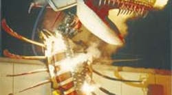
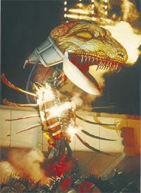
The fun and enjoyment of theme park shows and attractions tends to overshadow the innovative engineering that goes into them. Beneath the glamorous exteriors, these attractions usually challenge the very essence of the engineers who must transform concepts and ideas into nuts-and-bolts hardware.
As you would expect, safety and reliability are prime objectives. But these goals are meaningless unless the engineer comes up with something that actually works. This is where creativity and experience, lubricated with plenty of engineering know-how, become the basic tools for success.
When major new attractions are planned, Disney Imagineers become part of a team that develops ideas and sketches into spectacular attractions. After drawings, models, and prototypes have been developed and revised, the attraction comes into being. But when officials at the Walt Disney World Co. decide to develop a live show or special event, they often call on their Ride & Show Engineering Div. The division encompasses roughly 90 people, including engineers, managers, designers, technicians, and individuals representing a variety of subdivisions. One of these experts is Matt Lenz, senior engineer.
Defining the Project
Disney’s Creative Entertainment Div. had undertaken a project, and Lenz became involved midway through its development and helped orchestrate some pretty impressive results. The project, Splashtacular, opened in November 1993, to coincide with President Clinton’s proclamation of National Kid’s Day. The show made extensive use of music, dancing, and a spectacular fountain, provided by Walt Disney Imagineering, consisting of nearly 320 nozzles, some of which would shoot water 180 ft into the air. Lenz pointed out that this is as high as Spaceship Earth, the familiar silvery sphere that has become synonymous with EPCOT Center. He also revealed that pneumatics makes this incredible height possible by boosting pressure of the water behind the nozzles, “but that’s a different story altogether,” said Lenz.
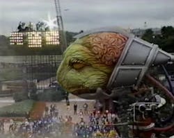
Ride & Show Engineering’s task was to design and construct the climax of the live show special effects: an alien space creature that would rise up out of the earth in a cloud of smoke and extend to a height of 65 ft. The project originally commissioned by Disney’s Creative Entertainment Div. had a 12-week schedule. However, six weeks into the project, the west-coast contractor supplying the monster informed Creative Entertainment that only the head of the monster could be delivered on schedule. This was when the Ride & Show Engineering Div. was called in to produce the design and Walt Disney World’s Central Shops was tapped to manufacture all of the monster except the head. Lenz said, “At that point we had about six weeks to come up with a complete design, build it, install it, test it, and integrate it with the show’s programming, dance routines, and other cues so it would fit into the system.”
Some parameters were defined when Lenz entered the project. A hydraulically actuated scissors-type lift in the bottom of a concrete pit would extend from a collapsed height of 3 ft to 18 ft to raise the monster into the view of spectators. Lenz explained that, “When the lift was raised to its full height, locking pins engaged sockets, so we didn’t depend on the hydraulic system for support. The lift platform then became a rigid structural floor, upon which this huge monster operated.” As the lift extended, the monster simultaneously unfolded upward to a maximum height of 65 ft with lift and monster fully extended.
Working within Restrictions
Weight was a big issue with this design, because making the monster too heavy would have required a more powerful lift. The lift was designed for a maximum load of 20,000 lb, so the total weight of the monster — including the head — could not exceed this value. Hydraulic power units (HPUs) had already been specified and were under construction, so the design would have to operate within the pressure and flow capabilities of the HPUs originally prescribed.
Lenz elaborated: “At one point, we had estimated that the monster would end up weighing somewhere around 23,000 lb instead of 20,000. We absolutely couldn’t reduce weight once we had all the hardware built, so we found ways of cutting 100 lb here or 40 lb there. But 3000 lb was an awful lot to get rid of. We ended up weighing every piece of structure that went on the system. The only thing we didn’t weigh was the fluid in the hoses, tubing, and cylinders. After calculating and adding in the weight of the fluid, we arrived at a final weight of 19, 995 lb!
“During all this, the lift manufacturer played it safe and smart and said they could not increase hydraulic pressure or resize anything to make the lift handle any more than 20,000 lb. They did tell us, however, that we’d need the greatest lifting force when the lift first started from a fully retracted position. As with all structures like this, at low angles, the effective force from the cylinders to drive the lift up vertically is at a minimum. But because the monster was so huge, we had to retract the lift all the way to get it out of sight. We developed a contingency plan to integrate some auxiliary cylinders that would help lift the monster when the scissors lift was fully retracted. Once the lift extended, its cylinders acted on a more effective angle.”
Early Development
Perhaps the most impressive accomplishment of the project was the short time in which a one-of-a-kind monster was developed. “Emmett Peter, manager of Engineering Services, brought four key engineers together and had a brief discussion,” recalled Lenz. “He told us what we had to accomplish, and outlined responsibilities for each of our respective areas. I was assigned the design of the entire hydraulic system, as well as the main structure beyond what was being supplied. Staff Engineer Mario Scarabino headed a fantastic team of engineers and designers assigned to specific parts of the project. That team and the fabrication team in Central Shops worked virtually around the clock until completion.
“I think the most amazing technological feat about this project,” continued Lenz, “was that in just 29 days from the day I started working on it, we had designed and fabricated the system, built the majority of the equipment, and installed enough hose, tubing, actuators, valves, and electrical controls to run our first system test.” Aside from the cooperation and dedication of all involved, an innovative idea was the key to this success.
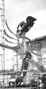
The design team studied the concepts established by Creative entertainment and determined that the monster would be able to turn left and right and pivot forward and backward on its base. A joint at the end of an extension from the base (serving as framework for the lower torso) would allow an upper extension (framework for the upper torso) to pivot up and down. A final joint on the end of this upper extension would allow the head to pivot up and down in a nodding-type motion. Provision for pivoting the head left and right on top of this joint was integral to the head being furnished.
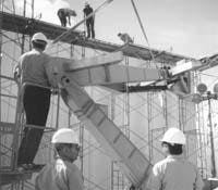
These four axes of motion (base turning, lower extension pivot, upper extension pivot, and head pivot) are identical to the movements of an excavator arm on a backhoe. The design team realized that using an existing backhoe arm would speed up the production process considerably by eliminating many design and fabrication steps. Their task then was to find just the right excavator arm that would handle the loads, speeds, and motions required. Their search led to a John Deere 490D backhoe.
“We decided to use that structure because it was about the right size we needed and had proven to be able to carry loads of the type and magnitude that we were working with,” explained Lenz. “The fact that it was an off-the-shelf item certainly made it attractive time-wise. Fred Sollie, an engineer with the Live Show Design Div., did some background work on the 490D. He rented a John Deere 490D backhoe, brought it on site, and all the engineers that were involved in the project got into the tractor and took turns running it just to get a feel for what kind of a structure we were dealing with. Once the team was assembled, we each took off in our own given direction.”
Forgotten movie star aids project
Sometimes improvisation is an engineer’s greatest tool. Faced with a six-week deadline to design the structure and hydraulic system for the fearsome-looking creature pictured on the front page of this article, Matt Lenz, senior engineer, had a system ready for testing only in 29 days. But one obstacle remained: How do you accurately test the system when the nearly 3/4-ton head is not scheduled for completion for a few more weeks? The answer: Make do with what you have.
Disney’s Ride & Show Engineering team found a discarded prop that seemed to be about the same size and weight as the head — the hulk of Herbie the Love Bug, a 1960’s Volkswagen beetle. After sustaining damage, it had been taken out of commission months earlier and was stored in a backlot to await its fate. Senior Engineer Jeff Hudson verified the weight distribution of the head under construction, and then strategically welded additional steel into the VW and made modifications to its frame in order to bolt it onto the monster body. Once the heavyweight VW was mounted, dynamic tests were conducted that verified the design goals had been achieved, Finally, the real head arrived to replace Herbie and the show opened on schedule.
Construction and Operation
The quick turnaround essential to the project meant that some original design requirements were revised. Lenz said, “We sat down with the people from Creative Entertainment to establish what the monster had to do as opposed to what they’d like it to do, time permitting. This allowed me more freedom in designing — a luxury that probably every engineer likes to have. We were almost defining our own specifications for speed, pressure, travel distance, and so on, as the project progressed. About the only constraints we had were weight, and the pressure and flow capabilities of the HPU. Of course, one of the other team members verified everyone else’s work, so nothing was overlooked.”
The backhoe comprised the lower body and the torso of the monster. The joints worked much like a shoulder at the base, an elbow in the middle, and a wrist at the top. Lenz revealed, “We figured the backhoe’s pivot points could take any side loads generated, but an engineer verified every structural element that we were using. I also was involved in determining the static and dynamic loads simply because these figures were needed for designing the hydraulic system and selecting components. If we weren’t satisfied with the integrity of any material or element, we redesigned that particular component.
“I designed my own redundant hydraulic system to integrate with the John Deere backhoe structure. I took out everything hydraulic that came on the structure and put in my own system, including cylinders and proportional valves. One of the first things I did was make real rough estimates of cylinder size, because the cylinders would dictate the size of all other hydraulic components in the system. We knew what the structure would basically look like, and we had some data on the masses of the head and the John Deere elements.
“The cylinders carried the longest lead time of all the elements, because they needed some modifications for mounting. I decided on NFPA-style [tie-rod] cylinders, because they are so readily available. We might have to wait to have modifications made, but we wouldn’t lose any time waiting for the cylinders themselves. After getting a rough size of the cylinders, I verified dynamic loads. To do this, part of our team locked ourselves in a room with representatives from the hydraulic component manufacturers and distributors to grind out the specifications. The cylinders could then be resized based on these dynamic loads. From that point on, everything almost fell right into place. We didn’t have a day to waste, so once I finished calculating dynamic load and sizing the cylinder, I passed my data on to the manufacturer’s rep, who would verify the size of the valves based on the speed, flow, and pressure. It worked very well, almost like an assembly line.”
Motion and Control
Lenz decided right away to use electrohydraulic proportional valves and designed them into the system at the very beginning. The system had to run smoothly, ramping up to constant velocity, then ramping down. So one of the first things he did was establish velocity curves for each of the functions.
In the theme park business, viewers often can distinguish good characters from evil ones just by the way they move. Good characters usually have smooth, fluid motion that is pleasing to the eye, while evil characters move in harsh, almost jerky motions. Even though the monster is one of the bad guys, the designers wanted it to have smooth smooth motions, possibly to give it the moves of a live creature even though it obviously was a machine. Lenz explained, “I relied on adjustments in the valve amplifier cards to make motions start and stop smoothly and to control how much basic proportional control we actually got. I had used this technique before, so I could vouch for its success and versatility.
The monster itself encompassed eight axes of hydraulic motion:
1. left and right turning at the base,
2. up and down pivot at the base,
3. up and down pivot at the joint between upper and lower body sections,
4. up and down head nodding at the top of the upper body (a platform that replaced the bucket of the backhoe, upon which the head was mounted),
5. left and right head turning (integral to the head),
6. head tilt (leveling), which is done automatically
7. left set of wings in and out, and
8. right set of wings in and out.
The wings were synchronized to move forward and backward at the same rate. The hardware encompassed two separate systems: two valves, two sets of cylinders, and two controls that run in parallel. Rather than using a lot of complicated hydraulic or electronic controls to keep the wings synchronized, Lenz again relied on tuning the valve driver cards and flow controls so that one input signal produced synchronized motion of the left and right blades. If one side tended to move slower than the other, tuning one of the cards would speed up or slow down one set of blades.
Two puppeteers operating six different multiple-function joysticks run the monster. Because the character is not run by a computer, every show is live and unique. “Operating the monster by a puppeteer was one of the original requirements of the show and was a big reason the team was able to get the project up and running so quickly,” Lenz explained. “However, the controls engineer, Kevin Schultz, implemented a sophisticated envelope-protection scheme to prevent motion in certain areas. His design depended on linear feedback sensors within the cylinders sending data to a PLC that he programmed with the operating envelope. The complexity and accuracy of the envelope protection was amazing.”
Matt Lenz, senior engineer assigned to Ride & Show Engineering Div., Walt World Disney Co., Lake Buena Vista, Fla.; Thom Pawlyn, market sales specialist, animation/simulation, Vickers Inc., Troy, Mich.; and Brian Poole, sales engineer, Hydraulic Supply, Orlando, Fla., provided technical details for this article.
