Water rides are a great way to beat the summer heat and have a lot of fun while you’re at it. Trouble is, once your ride of less than a minute is over, you have to tackle dozens of flights of stairs to do it again.
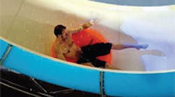
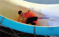
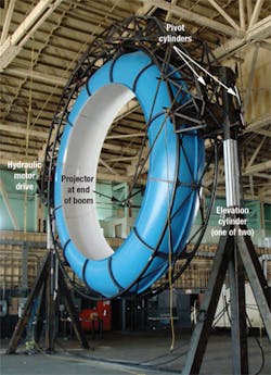
But that may become a thing of the past if a prototype simulator catches on. Imagine a water slide course 450-ft high and 3600-ft long — essentially, an endless water slide that could actually fit in your back yard. A prototype of this concept was presented on the Discovery Channel’s Prototype This program. Prototype This is a series where a group of engineers and scientists can design and build prototypes that solve the world’s problems or are just plain cool.In one of the show’s recent episodes, a computer projects an image of a water slide course inside a hollow fiberglass ring 30 ft in diameter, Figure 1. The rider and a small amount of water are inside the ring, so spinning the ring creates the sensation of moving through a water slide course. Raising and lowering the ring provides the G forces to simulate going over a waterfall, and tilting the ring from horizontal gives the impression of turning left or right. All that’s left, then, is to synchronize all this motion with a video presentation that’s projected on the inner surface of the ring, just ahead of the rider.
Hydraulics was selected to power the system because of the sheer mass of this machine. The ring itself weighs about 6000 lb, and lifting and tilting such a massive load smoothly and precisely with frequent and rapid changes in direction made hydraulics the best choice of power transmission. Electric motors could have been used to spin the ring, but because hydraulic cylinders were chosen to lift and tilt the ring, the design team chose instead to drive a friction wheel with a hydraulic motor to rotate the ring at speeds up to 10 rpm.
Power and control
Two pairs of hydraulic cylinders provide the thrust and motion to raise and lower the ring and tilt it up to 15° from vertical as it rotates. Each cylinder is considered a motion axis because it must move in precise synchronization not only with the ride video, but with each other. Otherwise, cylinder forces could create stresses to break the framework apart.
A challenge to synchronizing the motion stems from two different cylinder mounting configurations used. The elevation cylinders work as a pair, so each must extend or retract the same distance within a tight tolerance. The cylinders that tilt the ring, on the other hand, have opposed mounting — as one extends the other retracts. This means the proportional valves feeding the two cylinders must open different amounts because one routes fluid to the rod end of a cylinder while the other routes fluid to the cap end of the other cylinder.
The motion axis of the hydraulic motor works independent of the cylinder axes, but motion of all five axes must be coordinated with the video program. A sixth, a virtual axis, serves this function of coordinating the motion of the physical axes with the images projected onto the inner surface of the ride.
Input from the distributor
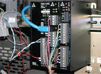
Mike Rogers, of Hydraulic Controls Inc. (HCI), a Walnut, Calif.-based Delta Computer Systems distributor, recommended the Delta RMC150 motion controller and provided most hydraulic components, including the HPU, for the project. Parker supplied the cylinders. To control and synchronize all the motion axes, the Prototype This team selected the RMC150 motion controller, Figure 2, which is capable of controlling and synchronizing up to eight hydraulic axes simultaneously.
Once the motion was tuned and programmed, a “Move” command was simultaneously issued to the RMC150 to start the motion sequence and to a video player to start the ride video.
The data points corresponding to targets for the motion of the water slide ring were generated by Zoz Brooks, MIT Robotics expert and co-host of Prototype This. He analyzed the position of the virtual camera in the ride video and produced about 50,000 position data points, which were reduced by the design team to approximately 1000 points representing one target point for every 180 msec.
Corresponding to each point is a data set composed of a lift, tilt, and rotational velocity value. The motion controller uses its spline functions to produce motion on each axis that “connects the dots” between the video frames with a smooth sequence of tilting, lifting, and spinning motion.
Dealing with spring effects
If that’s all that the controller and the system designers had to do, the design would have been straightforward. However, as is often the case in real life, there were some hydraulic system design challenges.
A key issue was what is often referred to as a spring effect. As constructed, the project had 50 ft of hydraulic hose between the proportional valves and the hydraulic cylinders on the structure. The effect of all that hose caused the cylinders to lag behind their target motion due to the expansion and contraction of the hose as the hydraulic pressure changed within the hoses.
This resulted in a system impossible to control using a simple PID control algorithm. The designers could have used a very low proportional gain to make the system more sluggish, thereby compensating for the spring effect. But this would have compromised performance of the application. In retrospect, the hydraulic valves should have been mounted directly on the cylinders, but this was a prototype that was built quickly, and this detail was overlooked for the sake of expediency.
Delta Computer Systems was called in to do the machine control programming and axis tuning. This included fixing the problem caused by the long hoses. The solution to this problem was accomplished in software by enabling a second derivative gain in the control algorithm. The Delta RMC has an option that supports acceleration control (the control algorithm used is a PID+D2, rather than a PID), which works to reduce the error between the actual acceleration of an axis and the target acceleration at any point in the motion profile. This results in an early speedup or slowdown of an axis’ motion when it starts lagging behind.
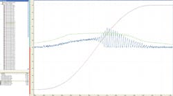
During the gain setting process we took advantage of the Delta RMC Plot Manager to determine the value of the second derivative gain (D2). To set D2, we ran some experiments; trying different values and plotting the results with Delta’s RMCTools software package, Figure 3. After doing this, we noticed that the system had become very sensitive to small changes in axis position feedback, which required filtering of the motion controller drive output to reduce the noise.
Final fixes
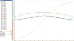
To further ensure that the system would respond quickly to the changing target motion profile, a feed forward gain parameter was added to the control algorithm, Figure 4. A feed forward term is a predictive element in the control loop equation that anticipates what the control output of the system needs to be (the other gain parameters in the equation work to reduce errors, not to predict what the motion needs to be). As the parameters were tuned, we watched the graphs produced by RMCTools to see if control was improved. When the tuning was done, the control of the system was both responsive and ran “as smooth as silk.”
So far, the “virtual water slide” prototype is one of a kind, but it shows the advantages of hydraulics in supporting motion simulators that can move large loads very smoothly and give a very realistic ride.
For more information contact the author at [email protected], call (360) 254-8688, or visit www.deltamotion.com.
